Redox Reactions by Transfer of Electrons at a Distance

Redox Reactions by Transfer of Electrons at a Distance

  • In all redox reactions, electrons are transferred from the reducing agent to the oxidising agent.
  • When the reducing and oxidising agents are mixed together as in the previous reactions, the transfer of electrons occurs quickly and cannot be detected.
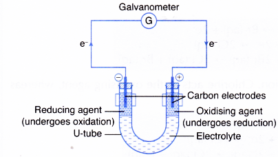
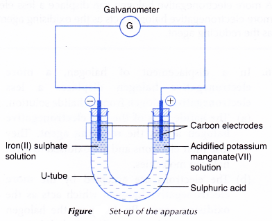
  • However, when the reducing and oxidising agents are separated by an electrolyte in a U-tube as shown in Figure 3.6, the transfer of electrons occurs through the connecting wires and can be detected by a galvanometer.
    Redox Reactions by Transfer of Electrons at a Distance 1
  • The reducing agent loses its electrons and hence undergoes oxidation. The electrode at which electrons are released by the reducing agent is called the negative terminal.
  • The electrons then flow through the connecting wires to the oxidising agent. The electrode at which electrons are accepted by the oxidising agent is called the positive terminal.
  • As the oxidising agent accepts the electrons, it undergoes reduction.
  • The electrolyte allows the movement of ions to take place, thus completing the electric circuit. This ensures a continuous flow of electrons in the external circuit.


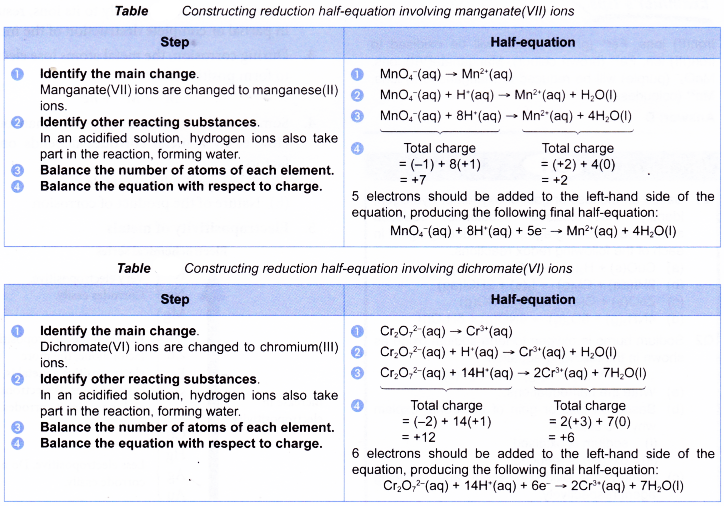
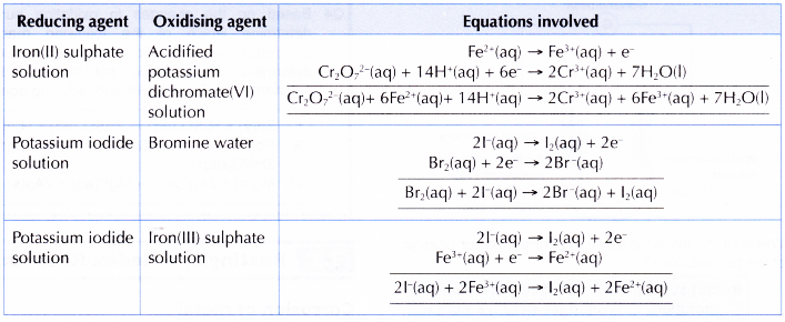
When polyatomic ions such as manganate(VII) ion and dichromate(VI) ion are involved in redox reactions, the half-equations are more complex. The following tables illustrate how the half-equations are constructed.
Redox Reactions by Transfer of Electrons at a Distance 2

People also ask

Oxidation and reduction in the transfer of electrons at a distance experiment

Aim: To investigate oxidation and reduction in the transfer of electrons at a distance.
Materials: 2.0 mol dm-3 sulphuric acid, 0.5 mol dm-3 freshly prepared iron(II) sulphate solution, 0.2 mol dm-3 acidified potassium manganate(VII) solution, 0.5 mol dm-3 potassium iodide solution, 0.2 mol dm-3 acidified potassium dichromate(VI) solution, 0.2 mol dm-3 potassium thiocyanate solution, 1% starch solution.
Apparatus: U-tube, galvanometer, connecting wires with crocodile clips, carbon electrodes, retort stand and clamp, test tube, dropper, stoppers with one hole.
Procedure:

  1. A U-tube is clamped to a retort stand.
  2. Dilute sulphuric acid is poured into the U-tube until its levels are 6 cm away from the mouths of the U-tube.
  3. Using a dropper, 0.5 mol dm-3 iron(II) sulphate solution is carefully added to one of the arms of the U-tube until the layer of iron(II) sulphate solution reaches the height of 3 cm.
    Redox Reactions by Transfer of Electrons at a Distance 3
  4. In a similar manner as in step 3, 0.2 mol dm-3 acidified potassium manganate(VII) solution is added to the other arm of the U-tube.
  5. A carbon electrode is placed in each arm of the U-tube.
  6. The electrodes are connected to a galvanometer as shown in Figure. Based on the deflection of the galvanometer, the electrodes that act as the positive terminal and negative terminal are determined.
  7. The set-up is left aside for 30 minutes. Any change is observed.
  8. Using a clean dropper, 1 cm3 of iron(II) sulphate solution is drawn out and placed in a test tube. Then, a few drops of 0.2 mol dm-3 potassium thiocyanate solution are added to the test tube. Any change is observed.
  9. Steps 1 to 7 are repeated using 0.5 mol dm-3 potassium iodide solution and 0.2 mol dm-3 acidified potassium dichromate(VI) solution to replace the iron(II) sulphate solution and acidified potassium manganate(VII) solution. Step 8 is repeated to test the potassium iodide solution with 1 % starch solution.
Results:

1. Solutions used: Iron(II) sulphate solution and acidified potassium manganate(VII) solution

ObservationInference
(a) The electrode in the iron(II) sulphate solution acts as the negative terminal while the electrode in the acidified potassium manganate(VII) solution acts as the positive terminal.Electrons flow from iron(II) sulphate solution to acidified potassium manganate(VII) solution.
(b) Iron(II) sulphate solution changes from pale green to yellow. It gives blood-red colouration with potassium thiocyanate solution.At the end of the reaction, iron(III) ions are present. Iron(II) ions have changed to iron(III) ions.
(c) The purple acidified potassium manganate(VII) solution decolourises.Manganate(VII) ions that give the solution its purple colour are used up in the reaction.

2. Solutions used: Potassium iodide solution and acidified potassium dichromate (VI) solution

ObservationInference
(a) The electrode in the potassium iodide solution acts as the negative terminal, whereas the electrode in the acidified potassium dichromate(VI) solution acts as the positive terminal.Electrons flow from potassium iodide solution to acidified potassium dichromate(VI) solution.
(b) The colourless potassium iodide solution turns brown. It gives a dark blue colouration with starch solution.At the end of the reaction, iodine is present. Iodide ions have changed to iodine.
(c) Potassium dichromate(VI) solution changes colour from orange to green.Dichromate(VI) ions have changed to chromium(lll) ions.

Discussion:

1. Iron(II) sulphate solution and acidified potassium manganate(VII) solution
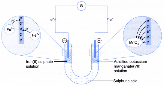
(a) Iron(II) ions act as the reducing agent, releasing electrons to become iron(III) ions. Thus, iron(II) sulphate solution changes colour from pale green to yellow.
Redox Reactions by Transfer of Electrons at a Distance 4
(b) The electrons accumulate at the carbon electrode in the iron(II) sulphate solution and flow out to the connecting wires. This carbon electrode acts as the negative terminal.
(c) The electrons then flow to the positive terminal, which is the carbon electrode in the acidified potassium manganate(VII) solution.
(d) Manganate(VII) ions act as the oxidising agent, accepting the electrons and therefore, undergoing reduction to become colourless manganese(II) ions.
Redox Reactions by Transfer of Electrons at a Distance 5
(e) The overall ionic equation is as follows:
Redox Reactions by Transfer of Electrons at a Distance 6

2. Potassium iodide solution and acidified potassium dichromate(VI) solution
Redox Reactions by Transfer of Electrons at a Distance 7
(a) Iodide ions act as the reducing agent, releasing electrons to become iodine molecules. Thus, the colourless potassium iodide solution turns brown.
Redox Reactions by Transfer of Electrons at a Distance 8
(b) The electrons accumulate at the carbon electrode in the potassium iodide solution and flow out to the connecting wires. This carbon electrode acts as the negative terminal.
(c) The electrons then flow to the positive terminal, which is the carbon electrode in the acidified potassium dichromate(VI) solution.
(d) Dichromate(VI) ions act as the oxidising agent, accepting the electrons and therefore, undergoing reduction to become chromium(III) ions.
Redox Reactions by Transfer of Electrons at a Distance 9
(e) The overall ionic equation is as follows:
Redox Reactions by Transfer of Electrons at a Distance 10
3. The continuous flow of electrons from the reducing agent at the negative terminal to the oxidising agent at the positive terminal produces an electric current that causes the indicator of the galvanometer to deflect.
4. Sulphuric acid has two functions:
(a) To separate the reducing agent from the oxidising agent
(b) To complete the circuit by .allowing the transfer of ions to occur
5. Other electrolytes such as potassium nitrate solution and sodium chloride solution can be used in place of sulphuric acid. The electrolyte should not react with either the reducing agent or the oxidising agent used.
6. There are few other pairs of reducing agent and oxidising agent that can be used in this activity. Here are some examples:
Redox Reactions by Transfer of Electrons at a Distance 11

Conclusion:
The transfer of electrons occurs from the reducing agent to the oxidising agent through the connecting wires.
Oxidation and Reduction in Chemical Cells

Oxidation and Reduction in Chemical Cells


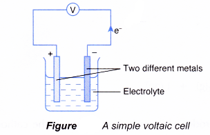
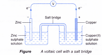
    • In a simple voltaic cell, two different metals are in contact with an electrolyte.
      Oxidation and Reduction in Chemical Cells 1
    • The more electropositive metal will become the negative terminal while the less electropositive metal will become the positive terminal.
  • The chemical change that takes place at each electrode is actually a half-reaction of a redox reaction. As a result of the redox reaction, a flow of electrons or an electric current is produced.
  • The set-up of a simple voltaic cell may also include a salt bridge or a porous pot. The salt bridge or porous pot separates the half-reactions while completing the circuit by allowing the movement of ions to take place.
    Oxidation and Reduction in Chemical Cells 2
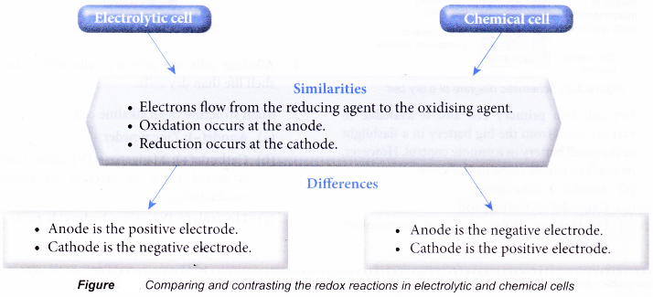
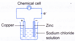
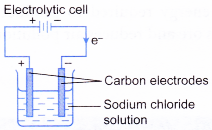
  • Figure compares and contrasts the redox reactions in electrolytic and chemical cells.

Oxidation and Reduction in Chemical Cells 3

People also ask

Oxidation and Reduction in Chemical Cells Experiment

Aim: To investigate the oxidation and reduction in chemical cells.
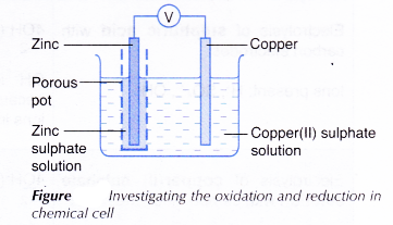
Materials: 1 mol dm-3 copper(II) sulphate solution, 1 mol dm-3 zinc sulphate solution, copper strip, zinc strip, sandpaper.
Apparatus: Porous pot, voltmeter, connecting wires with crocodile clips, beaker.
Procedure:

  1. Zinc sulphate solution is poured into a porous pot until three quarters full.
  2. The porous pot is placed in a beaker.
  3. Copper(II) sulphate solution is poured into the beaker until its level is the same as that of the solution in the porous pot.
  4. A strip of copper and a strip of zinc are cleaned with sandpaper.
  5. The two strips are connected as shown in Figure.
    Oxidation and Reduction in Chemical Cells 4
  6. The set-up of the apparatus is left aside for 20 minutes. Any changes are observed.

Observations:

  1. The voltmeter shows a reading.
  2. The deflection of the indicator of the voltmeter indicates that electric current flows from the copper strip to the zinc strip.
  3. The intensity of the blue colour of the copper(II) sulphate solution decreases with time.
  4. Brown solid is deposited on the copper strip.
  5. The zinc strip becomes thinner.

Discussion:

  1. Since electric current flows from the copper strip to the zinc strip, it is inferred that electrons flow from the zinc strip to the copper strip.
    Note: Conventionally, electrons flow in the opposite direction of electric current.
  2. This means that the zinc strip becomes the negative terminal while the copper strip becomes the positive terminal.
  3. (a) Zinc is more electropositive than copper. In other words, zinc can lose its electrons more readily than copper.
    (b) Therefore, zinc acts as the reducing agent, losing electrons to form zinc ions, Zn2+. This explains why the zinc strip becomes thinner.
    Oxidation and Reduction in Chemical Cells 5
    (c) The accumulated electrons cause the zinc strip to become the negative terminal.
    (d) By losing its electrons, zinc undergoes oxidation. Thus, the zinc strip also serves as the anode.
  4. The accumulated electrons then flow out of the zinc strip through the connecting wires to the copper strip. This makes the copper strip the positive terminal.
  5. At the positive terminal, copper(II) ions, Cu2+ from the electrolyte act as the oxidising agent by accepting the electrons. By doing so, Cu2+ ions are reduced to metallic copper.
    Oxidation and Reduction in Chemical Cells 6
  6. As reduction occurs at the copper strip, the copper strip is said to serve as the cathode.
  7. (a) Due to the decrease in the amount of Cu2+ ions in the solution, the intensity of the blue colour of the copper(II) sulphate solution slowly decreases.
    (b) Metallic copper that is produced forms a brown layer around the strip.
  8. In this chemical cell, electrons flow from zinc, the reducing agent at the anode or negative terminal, to Cu2+ ions, the oxidising agent at the cathode or positive terminal.

Conclusion:
In a chemical cell, oxidation occurs at the anode (negative terminal) while reduction occurs at the cathode (positive terminal).


Follow us on:

https://plus.google.com/+Veerendracbse
https://plus.google.com/+DurgaprasannaAmujuri
https://plus.google.com/+phanicbse
https://plus.google.com/+vinilachoudary
https://plus.google.com/+LearnCbseind
https://plus.google.com/+kajalsharmaLearnCBSE
https://plus.google.com/+sravyasharma
https://plus.google.com/+kajalsharmaLearnCBSE
https://plus.google.com/+cbseguesspapersfree
https://plus.google.com/+CharanSing
https://plus.google.com/+rajuheal
https://plus.google.com/+saralasharma
https://plus.google.com/+mastiaddaLearnCBSE
https://plus.google.com/+ChandraRamLearnCBSE
https://plus.google.com/+AmrutPandey
https://plus.google.com/+VenkataLakshmiLearnCBSE
https://plus.google.com/+nagaRajuLearnCBSE
https://plus.google.com/+SekharThe
https://plus.google.com/+TriveniMcc

Oxidation and Reduction in Electrolytic Cells

Oxidation and Reduction in Electrolytic Cells


  • In an electrolytic cell, an electric current is passed through an electrolyte using electrodes.
  • The electrolyte may be a molten ionic compound or an aqueous solution containing ions.
  • The electrodes are usually inert conductors such as platinum or carbon. Sometimes active electrodes such as copper are used.
  • During electrolysis, the electrolyte undergoes chemical changes at the electrodes. The chemical change at each electrode is actually a half-reaction of a redox reaction.
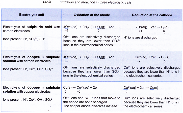
  • The following table shows the oxidation and reduction in a few other electrolytic cells.

Oxidation and Reduction in Electrolytic Cells 1

  • In all electrolytic cells, electrons flow from the reducing agent at the anode to the oxidising agent at the cathode.
  • The reducing agent loses electrons and undergoes oxidation at the anode.
  • On the other hand, the oxidising agent gains electrons and undergoes reduction at the cathode.

People also ask

Oxidation and Reduction in Electrolytic Cells Experiment

Aim: To investigate the oxidation and reduction in electrolytic cells.
Materials: Solid lead(II) bromide, 1 mol dm-3 potassium iodide solution, 1% starch solution, sandpaper, wooden
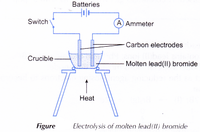
Apparatus: Crucible, cardboard, battery, connecting wires with crocodile clips, tripod stand, Bunsen burner, pipe-clay triangle, electrolytic cell, carbon electrodes, switch, ammeter, small test tubes, beaker, tongs.
Procedure:
A. Electrolytic cell involving molten electrolyte

  1. A crucible is half-filled with solid lead(II) bromide.
  2. The apparatus is set up as shown in Figure.
    Oxidation and Reduction in Electrolytic Cells 2
  3. The solid lead(II) bromide is heated until it is completely melted.
  4. The switch is turned on to allow electricity to pass through the molten lead(II) bromide for about 20 minutes. Any changes are observed.
  5. After 20 minutes, the switch is turned off and both electrodes are taken out from the electrolyte. The molten electrolyte is carefully poured into a beaker using tongs. The product left at the bottom of the crucible is observed.

B. Electrolytic cell involving aqueous electrolyte

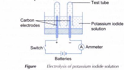
  1. An electrolytic cell is half-filled with 0.5 mol dm-3 potassium iodide solution.
  2. The apparatus is set up as shown in Figure.
    Oxidation and Reduction in Electrolytic Cells 3
  3. The switch is turned on to allow electricity to pass through the electrolyte for 15 minutes. Any changes at the anode and cathode are observed.
  4. The product at the anode is tested with 1 % starch solution while the gas collected at the cathode is tested with a lighted wooden splinter.

Results:
A. Electrolytic cell involving molten electrolyte

ElectrodeObservationInference
AnodeA brown gas with a pungent and choking smell is released.Bromine gas is released.
CathodeA shiny grey globule is found at the bottom of the crucible.Lead is produced.

B. Electrolytic cell involving aqueous electrolyte

ElectrodeObservationInference
AnodeThe solution in the test tube turns from colourless to brown.
It gives a dark blue colouration when tested with starch solution.
Iodine is produced.
CathodeGas bubbles are released. A colourless gas which burns with a ‘pop’ sound is produced.Hydrogen gas is produced.

Discussion:

  1. In the electrolysis of molten lead(II) bromide:
    (a) Molten lead(II) bromide contains lead(II) ions, Pb2+ and bromide ions, Br.
    (b) Pb2+ ions move to the cathode while Br ions move to the anode.
    (c) At the anode, Br ions act as the reducing agent, losing electrons to become bromine molecules. Thus, Br ions undergo oxidation.
    Oxidation and Reduction in Electrolytic Cells 4
    At the cathode, Pb2+ ions act as the oxidising agent, accepting electrons to become metallic lead. Thus, Pb2+ ions undergo reduction.
    Oxidation and Reduction in Electrolytic Cells 5
    (d) Hence, electrons are transferred from Br ions, the reducing agent, at the anode to Pb2+ ions, the oxidising agent, at the cathode.
    (e) The overall equation is as follows.
    Oxidation and Reduction in Electrolytic Cells 6
  2. In the electrolysis of potassium iodide solution:
    (a) Potassium iodide solution contains hydrogen ions, H+, potassium ions, K+, hydroxide ions, OH and iodide ions, I.
    (b) H+ ions and K+ ions move to the cathode while OH ions and I ions move to the anode.
    (c) At the anode, I ions are selectively discharged because of their high concentration in the electrolyte. I ions act as the reducing agent, losing electrons to become iodine molecules. In other words, I ions undergo oxidation.
    Oxidation and Reduction in Electrolytic Cells 7
    (d) At the cathode, H+ ions are selectively discharged because their position in the electrochemical series is lower than Kions. H+ ions act as the oxidising agent, gaining electrons to become hydrogen molecules. In other words, H+ ions undergo reduction.
    Oxidation and Reduction in Electrolytic Cells 8
    (e) The overall equation is as follows.
    Oxidation and Reduction in Electrolytic Cells 9

Conclusion:
In an electrolytic cell, oxidation occurs at the anode (positive electrode) while reduction occurs at the cathode (negative electrode).

Changing of iron(II) ions to iron(III) ions and vice versa

Changing of iron(II) ions to iron(III) ions and vice versa

  1. Iron exhibits two oxidation numbers
    (a) +2 as iron(II) ion, Fe2+
    (b) +3 as iron(III) ion, Fe3+
  2. An aqueous solution containing iron(II) ions, Fe2+ is pale green in colour, whereas that containing iron(III) ions, Fe3+ is yellow/yellowish-brown/ brown in colour.
  3. Changing iron(II) ions to iron(III) ions is an oxidation and therefore requires an oxidising agent.
    Changing of iron(II) ions to iron(III) ions and vice versa 1
  4. On the other hand, changing iron(III) ions to iron(II) ions is a reduction and therefore requires a reducing agent.
    Changing of iron(II) ions to iron(III) ions and vice versa 2


Table: Detecting the presence of iron(II) ions and iron(III) ions

ReagentWith iron ionsObservation
Sodium hydroxide solution or ammonia solutionFe2+Green precipitate, insoluble in excess alkali
Fe3+Brown precipitate, insoluble in excess alkali
Potassium hexacyanoferrate(ll) solutionFe2+Light blue precipitation
Fe3+Dark blue precipitation
Potassium hexacyanoferrate(lll) solutionFe2+Dark blue precipitation
Fe3+Greenish-brown solution
Potassium/ammonium thiocyanate solutionFe2+Pale red colouration
Fe3+Blood-red colouration

The following are other oxidising agents that can replace bromine water in changing iron(II) ions to iron(III) ions.
Changing of iron(II) ions to iron(III) ions and vice versa 3

Other reducing agents that can replace zinc powder in changing iron(III) ions to iron(II) ions are as follows.
Changing of iron(II) ions to iron(III) ions and vice versa 4

People also ask

Changing of iron(II) ions to iron(III) ions and vice versa experiment

Aim: To investigate oxidation and reduction in the change of iron(II) ions to iron(III) ions and vice versa.
Materials: 0.5 mol dm-3 freshly prepared iron(II) sulphate solution, 0.5 mol dm-3 iron(III) sulphate solution, bromine water, zinc powder, 2.0 mol dm-3 sodium hydroxide solution, filter paper.
Apparatus: Dropper, spatula, test tubes, test tube holder, Bunsen burner, filter funnel, test tube rack.
Procedure:
A. Changing of iron(II) ions to iron(III) ions

  1. 2 cm3 of 0.5 mol dm-3 iron(II) sulphate solution is poured into a test tube.
  2. Using a dropper, bromine water is added to the solution drop by drop.
  3. The test tube is warmed gently.
  4. 2.0 mol dm-3 sodium hydroxide solution is added slowly to the mixture until in excess.

B. Changing of iron(III) ions to iron(II) ions

  1. 2 cm3 of 0.5 mol dm-3 iron(III) sulphate solution is poured into a test tube.
  2. Half a spatula of zinc powder is added to the solution.
  3. The mixture is filtered.
  4. 2.0 mol dm-3 sodium hydroxide solution is added slowly to the filtrate until in excess.

Observations:

ActivityReagentObservations
ABromine waterBromine water decolourises. The solution changes colour from pale green to yellow.
Sodium hydroxide solutionBrown precipitate is formed. It is insoluble in excess alkali.
BZinc powderSome of the zinc powder dissolves. The solution changes colour from brown to pale green.
Sodium hydroxide solutionGreen precipitate is formed. It is insoluble in excess alkali.

Discussion:
A. Changing of iron(II) ions to iron(III) ions

  1. Bromine water oxidises iron(II) ions, Fe2+ to iron(III) ions, Fe3+. The presence of Fe3+ ions is confirmed by the formation of brown precipitate with sodium hydroxide solution.
  2. Fe2+ ions lose their electrons and are oxidised to Fe3+ ions.
  3. Bromine molecules, which give the bromine water its brown colour, gain the electrons and are reduced to colourless bromide ions, Br. This explains why the bromine water is decolourised.
  4. In this reaction, bromine water acts as the oxidising agent, where as Fe2+ ions act as the reducing agent.
    Changing of iron(II) ions to iron(III) ions and vice versa 5

B. Changing of iron(III) ions to iron(II) ions

  1. Zinc powder reduces iron(III) ions, Fe3+ to iron(II) ions, Fe2+. The presence of Fe2+ ions is confirmed by the formation of green precipitate with sodium hydroxide solution.
  2. Zinc atoms lose their electrons and are oxidised to zinc ions, Zn2+. This explains why zinc powder dissolves in iron(III) sulphate solution.
  3. Fe3+ ions accept these electrons and are reduced to Fe2+ ions.
  4. In this reaction, Fe3+ ions act as the oxidising agent, whereas zinc acts as the reducing agent.
    Changing of iron(II) ions to iron(III) ions and vice versa 6

Conclusion:

  1. Bromine water acts as an oxidising agent, changing iron(II) ions to iron(III) ions.
  2. Zinc acts as a reducing agent, changing iron(III) ions to iron(II) ions.

Electrolytic and Chemical Cells

Electrolytic and Chemical Cells

  • Redox reaction occurs in both electrolytic and chemical cells.
  • An electrolytic cell is a device that uses electricity from an external source to drive a redox reaction.
  • On the other hand, a chemical cell is a device that uses redox reaction to produce electricity.
  • The two cells differ in the following aspects.
Electrolytic cellChemical cell
Basic structureIt requires a source of electric current.
The electrodes may be of the same or different materials.
It does not require a source of electric current.
The electrodes must be of two different materials.
Energy conversionThe supplied electrical energy causes chemical reactions to occur at the electrodes.
Electrical energy → chemical energy
The chemical reactions that occur at the electrodes produce an electric current.
Chemical energy → electrical energy
Tranfer of electronsElectrons flow from the positive electrode to the negative electrode through the connecting wires.Electrons flow from the more electropositive metal (negative terminal) to the less electropositive metal (positive terminal).
Electrolytic and Chemical Cells 1Electrolytic and Chemical Cells 2
  • For both electrolytic cell and chemical cell, the terms ‘anode’ and ‘cathode’ are assigned based on the reaction that occurs at the electrodes.
    • The electrode at which oxidation occurs is called the anode.
    • The electrode at which reduction occurs is called the cathode.

People also ask

Types of Chemical Cells

  • Chemical cells can be divided into two main types, namely primary cells and secondary cells.
  • Primary cells are not rechargeable and can be used only once. They have to be disposed of once they are exhausted or fully discharged.
  • Examples of primary cells are dry cells, alkaline cells and mercury cells.
  • Secondary cells are rechargeable when they are exhausted and can be used again and again.
  • Secondary cells can be recharged by passing an electric current through them in the opposite direction to the current flow during discharge or use.
  • Examples of secondary cells include lead-acid accumulator, nickel-cadmium cell and lithium- ion cells.

Dry cell

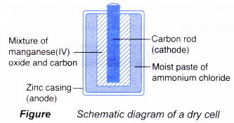
Dry cell is a primary cell and is available in various sizes, from the big battery in a flashlight to the small battery in a remote control. However, its main structure remains the same:
(a) Anode(-): Zinc casing
(b) Cathode(+): Carbon rod
(c) Electrolyte: Moist paste of ammonium chloride
Electrolytic and Chemical Cells 3
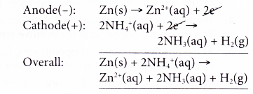
The reactions that occur during the use of a dry cell are as follows.

  • At the anode, zinc releases electrons and is oxidised to zinc ions. Thus, zinc acts as the reducing agent.
  • The electrons flow through the external circuit to the cathode.
  • At the cathode, ammonium ions act as the oxidising agent, accepting the electrons, and thus are reduced to hydrogen gas. The oxidation number of hydrogen decreases from +1 in ammonium ions to 0 in hydrogen gas.
  • Thus, the overall reaction is as follows.
    Electrolytic and Chemical Cells 4
    The hydrogen gas produced is eliminated by manganese(IV) oxide.

Alkaline cell

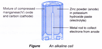
Alkaline cells are primary cells with a longer shelf life than dry cells.
Main structure of an alkaline cell:
(a) Anode(-): Zinc powder
(b) Cathode(+): Manganese(IV) oxide (carbon is added to it to increase its electrical conductivity)
(c) Electrolyte: Potassium hydroxide paste
Electrolytic and Chemical Cells 5
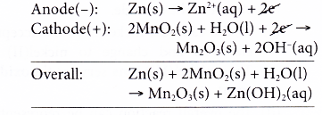
The reactions that occur during -the use of an alkaline cell are as follows.

  • At the anode, zinc powder acts as the reducing agent, losing electrons and is oxidised to zinc ions.
  • The electrons collected at the metal rod flow through external circuit to the cathode.
  • At the cathode, manganese(IV) ions, the oxidising agent, accept the electrons and are reduced to manganese(III) ions. The oxidation number of manganese decreases from +4 in manganese(IV) ions to +3 in manganese(III) ions.
  • Hence, the overall reaction is as follows.
    Electrolytic and Chemical Cells 6

Mercury cell

Very small button-shaped cells are needed for devices such as watches and cameras. One of the common button-shaped cells is mercury cell.
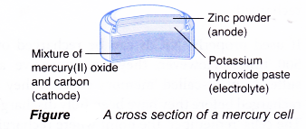
Main structure of a mercury cell:
(a) Anode(-): Zinc powder
(b) Cathode(+): Mercury(II) oxide (carbon is added to it to increase its electrical conductivity)
(c) Electrolyte: Potassium hydroxide paste
Electrolytic and Chemical Cells 7
The reactions that occur during the use of a mercury cell are as follows.

  • At the anode, zinc powder releases electrons and is oxidised to zinc ions. Thus, zinc acts as the reducing agent.
  • The electrons flow through external circuit to the cathode.
  • At the cathode, mercury(II) ions gain the electrons and are reduced to metallic mercury. Thus, mercury(II) ions are the oxidising agent.
  • The overall reaction is as follows.
    Electrolytic and Chemical Cells 8

The metallic mercury produced poses a danger to the environment. Hence, used mercury cells should be recycled. After collection, the cells are broken up and the mercury is recycled.

Lead-acid accumulator

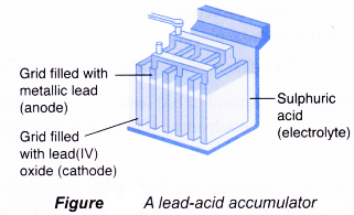
Lead-acid accumulator is rechargeable and is well known for its use as car battery.
Each cell has the following main structure:
(a) Anode(-): Metallic lead.
(b) Cathode(+): Lead(IV) oxide
(c) Electrolyte: Sulphuric acid
Electrolytic and Chemical Cells 9
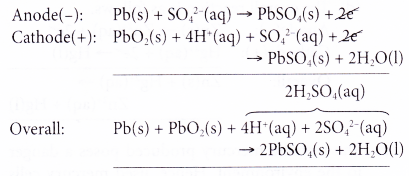
The reactions that occur during the discharge or use of a lead-acid accumulator are as follows.

  • At the anode, metallic lead acts as the reducing agent, releasing electrons to form lead(II) ions. This is an oxidation process.
  • The electrons released travel through the external circuit to run lights, starters or air- conditioner. The electrons then travel to the cathode to complete the circuit.
  • At the cathode, lead(IV) ions gain the electrons and are reduced to lead(II) ions. Thus, lead(IV) ions act as the oxidising agent.
  • Lead(II) ions formed at both anode and cathode combine with sulphate ions in the electrolyte to form insoluble lead(II) sulphate.
  • Hence, the overall reaction can be represented as follows.
    Electrolytic and Chemical Cells 10

As the redox reaction proceeds, both electrodes turn to lead(II) sulphate and the sulphuric acid turns to water. Thus, the accumulator slowly loses its power and eventually becomes ‘dead’.
When this happens, the accumulator can be recharged by passing an electric current in the opposite direction. This causes the reverse reaction to take place.
Electrolytic and Chemical Cells 11
Improper disposal of old lead-acid accumulators could lead to environmental hazard such as lead-poisoning.
In the recycling of lead-acid accumulators, the accumulators are broken, the electrolyte is neutralised and the lead is recovered through controlled processes. The lead is then refined for resale.

Nickel-cadmium cell

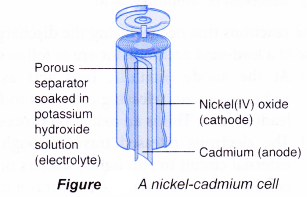
  • Nickel-cadmium cell, or commonly abbreviated as NiCd or NiCad, is a popular rechargeable battery for toys and electronic devices such as remote controls. They are available in various sizes and voltages.
  • Today, almost all NiCds use the ‘jelly-roll’ design whereby several layers of anode and cathode materials are rolled into a cylindrical shape.
  • Each cell has the following main structure:
    (a) Anode (-): Cadmium
    (b) Cathode(+): Nickel(IV) oxide
    (c) Electrolyte: Potassium hydroxide
    Electrolytic and Chemical Cells 12
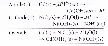
  • The reactions that occur during the discharge or use of a nickel-cadmium cell are as follows.
    (a) At the anode, cadmium releases electrons and thus becomes the reducing agent.
    (b) The electrons travel through the external circuit to the cathode.
    (c) At the cathode, nickel(IV) ions accept the electrons and change to nickel(II) ions. Thus, nickel(IV) ions serve as the oxidising agent.
    (d) The overall reaction can be represented as follows.
    Electrolytic and Chemical Cells 13
  • The overall reaction is reversed when the cell is recharged.
  • If used properly, NiCds can be recharged over 500 times. However, they are expensive and suffer from so-called ‘memory effect’ if they are recharged before they have been fully discharged. The cells ‘remember’ the point where recharging began and during subsequent use, they suffer a sudden drop in voltage at that point.
  • NiCds contain cadmium, which is a toxic heavy metal. Therefore, they should be disposed of properly. The heavy metal can be recovered through recycling.

Other chemical cells

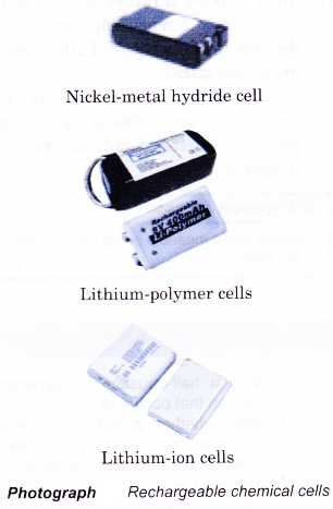
There are several new rechargeable chemical cells available in the market. These include the nickel-metal hydride, lithium-ion and lithium polymer cells.
Electrolytic and Chemical Cells 14

Nickel-metal hydride (NiMH)

  • NiMHs are similar to NiCds but they do not contain cadmium. Instead, they contain compounds of rare earth elements such as titanium, vanadium, zirconium, cobalt, manganese and aluminium. Thus, these cells are cheaper and considered more environmentally friendly.
  • NiMHs have higher capacity than’NiCds. Thus, they are usually used in high drain devices such as digital cameras and mobile phones.
  • They are less prone to memory effect but have a higher self-discharge rate than NiCds.

Lithium-ion (Li-Ion)

  • Currently, Li-Ion is the most popular rechargeable battery for mobile phones and notebook computers.
  • This is because Li-Ion is smaller and therefore lighter. Furthermore, it does not suffer memory effect like NiCds.
  • A Li-Ion has carbon as the anode and a metal oxide as the cathode. It has a special solid-state electrolyte, which is a lithium salt in an organic solvent-such as ether. The metallic lithium produced during use is very reactive and might cause explosion. Thus, a Li-Ion is inflammable and can easily explode when exposed to high temperature.
  • The shelf life of a Li-Ion is dependent upon aging from the time of manufacture, regardless of whether it is used or not.

Lithium-polymer (Li-Poly)

  • Li-Poly is a more advanced design of Li-Ion.
  • The difference is that the lithium salt electrolyte is not held in an organic solvent but is held in a solid polymer composite such as polyacrylonitrile. Hence, Li-Poly is not flammable.
  • Another advantage of Li-Poly is that it can be made very thin, small and light, a feature which is highly desired in portable electronic devices such as mobile phones, MP3 players and Bluetooth enabled devices.
  • Generally, almost all resources on earth are depleting. Hence, scientists are looking into possibilities of developing chemical cells such as fuel cells and solar cells as alternative sources of renewable energy.

Fuel cells

  • A fuel cell converts the chemical energy of a fuel such as hydrogen and natural gas to electricity.
  • A fuel cell consists of an anode (to which a fuel is supplied) and a cathode (to which air or oxygen is supplied) which are separated by an electrolyte.
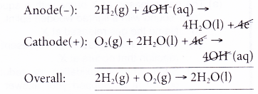
  • A hydrogen fuel cell runs on hydrogen which is obtainable from the electrolysis of water. Hydrogen is constantly fed to the anode while oxygen is constantly fed to the cathode.
    Electrolytic and Chemical Cells 15
    In this example, the only waste product is water, a non-polluting product.
  • Scientists are trying to make fuel cells economically competitive. At the moment, fuel cells are only used as an energy source in remote locations, such as in spacecraft, remote weather stations or in certain military applications.

Solar cells

  • Solar cells are made from thin slices of semiconductor materials such as crystalline silicon or gallium arsenide.
  • These cells are attractive as they can convert solar energy, a renewable source of energy, directly into electricity. Furthermore, they are pollution-free.
  • Due to high cost, solar cells are currently used to power orbiting space satellites, gates at unattended railroad crossings and irrigation pumps.

Follow us on:

https://plus.google.com/+Veerendracbse
https://plus.google.com/+DurgaprasannaAmujuri
https://plus.google.com/+phanicbse
https://plus.google.com/+vinilachoudary
https://plus.google.com/+LearnCbseind
https://plus.google.com/+kajalsharmaLearnCBSE
https://plus.google.com/+sravyasharma
https://plus.google.com/+dattuvalipishetty
https://plus.google.com/+kajalsharmaLearnCBSE
https://plus.google.com/+cbseguesspapersfree
https://plus.google.com/+CharanSing
https://plus.google.com/+rajuheal
https://plus.google.com/+saralasharma
https://plus.google.com/+mastiaddaLearnCBSE
https://plus.google.com/+ChinnaDarling
https://plus.google.com/+ChandraRamLearnCBSE
https://plus.google.com/+AmrutPandey
https://plus.google.com/+Rajashekharvalipishetty
https://plus.google.com/+VenkataLakshmiLearnCBSE
https://plus.google.com/+nagaRajuLearnCBSE
https://plus.google.com/+SekharThe
https://plus.google.com/+TriveniMcc