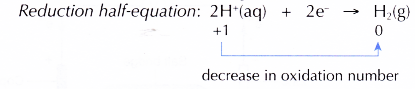
Redox Reactions by Transfer of Electrons at a Distance
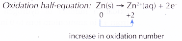
- In all redox reactions, electrons are transferred from the reducing agent to the oxidising agent.
- When the reducing and oxidising agents are mixed together as in the previous reactions, the transfer of electrons occurs quickly and cannot be detected.
- However, when the reducing and oxidising agents are separated by an electrolyte in a U-tube as shown in Figure 3.6, the transfer of electrons occurs through the connecting wires and can be detected by a galvanometer.
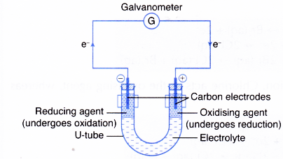
- The reducing agent loses its electrons and hence undergoes oxidation. The electrode at which electrons are released by the reducing agent is called the negative terminal.
- The electrons then flow through the connecting wires to the oxidising agent. The electrode at which electrons are accepted by the oxidising agent is called the positive terminal.
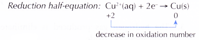
- As the oxidising agent accepts the electrons, it undergoes reduction.
- The electrolyte allows the movement of ions to take place, thus completing the electric circuit. This ensures a continuous flow of electrons in the external circuit.
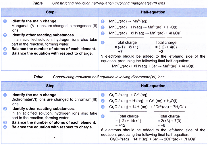
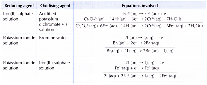
When polyatomic ions such as manganate(VII) ion and dichromate(VI) ion are involved in redox reactions, the half-equations are more complex. The following tables illustrate how the half-equations are constructed.
People also ask
- What is a redox reaction?
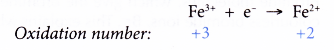
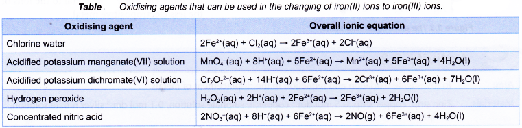
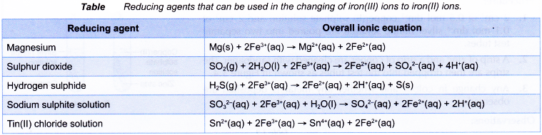
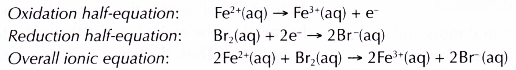
- Changing of iron(II) ions to iron(III) ions and vice versa
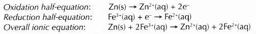
- Redox reaction in the displacement of metals from its salt solution
- Displacement of Halogen From Halide Solution
- Rusting as a Redox Reaction
- The Reactivity Series of Metals Towards Oxygen
- Application of the reactivity series of metals in the extraction of metals
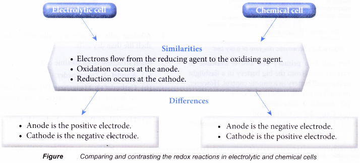
- Electrolytic and Chemical Cells
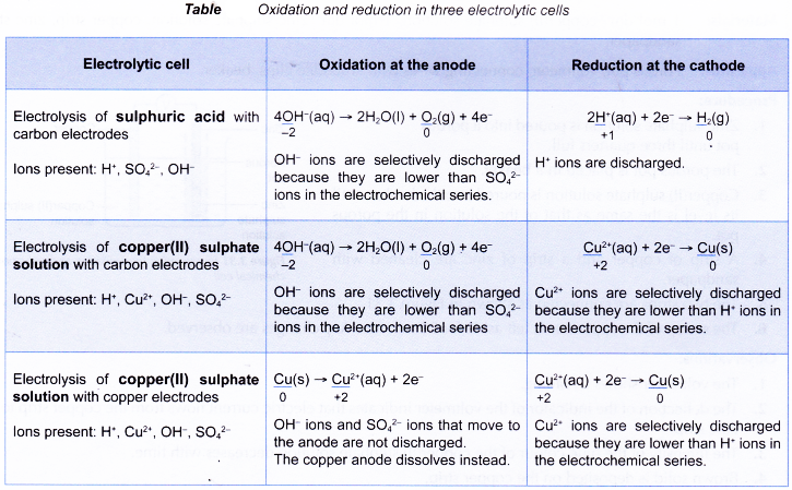
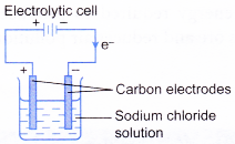
- Oxidation and Reduction in Electrolytic Cells
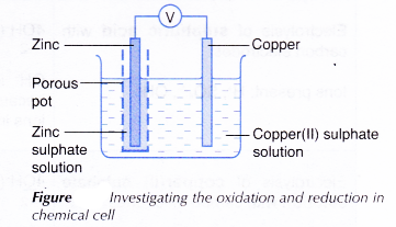
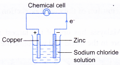
- Oxidation and Reduction in Chemical Cells
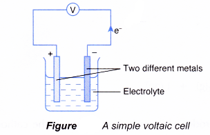
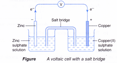
- How does a voltaic cell work?
Oxidation and reduction in the transfer of electrons at a distance experiment
Aim: To investigate oxidation and reduction in the transfer of electrons at a distance.
Materials: 2.0 mol dm-3 sulphuric acid, 0.5 mol dm-3 freshly prepared iron(II) sulphate solution, 0.2 mol dm-3 acidified potassium manganate(VII) solution, 0.5 mol dm-3 potassium iodide solution, 0.2 mol dm-3 acidified potassium dichromate(VI) solution, 0.2 mol dm-3 potassium thiocyanate solution, 1% starch solution.
Apparatus: U-tube, galvanometer, connecting wires with crocodile clips, carbon electrodes, retort stand and clamp, test tube, dropper, stoppers with one hole.
Procedure:
- A U-tube is clamped to a retort stand.
- Dilute sulphuric acid is poured into the U-tube until its levels are 6 cm away from the mouths of the U-tube.
- Using a dropper, 0.5 mol dm-3 iron(II) sulphate solution is carefully added to one of the arms of the U-tube until the layer of iron(II) sulphate solution reaches the height of 3 cm.
- In a similar manner as in step 3, 0.2 mol dm-3 acidified potassium manganate(VII) solution is added to the other arm of the U-tube.
- A carbon electrode is placed in each arm of the U-tube.
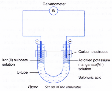
- The electrodes are connected to a galvanometer as shown in Figure. Based on the deflection of the galvanometer, the electrodes that act as the positive terminal and negative terminal are determined.
- The set-up is left aside for 30 minutes. Any change is observed.
- Using a clean dropper, 1 cm3 of iron(II) sulphate solution is drawn out and placed in a test tube. Then, a few drops of 0.2 mol dm-3 potassium thiocyanate solution are added to the test tube. Any change is observed.
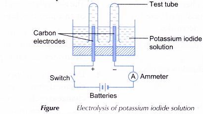
- Steps 1 to 7 are repeated using 0.5 mol dm-3 potassium iodide solution and 0.2 mol dm-3 acidified potassium dichromate(VI) solution to replace the iron(II) sulphate solution and acidified potassium manganate(VII) solution. Step 8 is repeated to test the potassium iodide solution with 1 % starch solution.
Results:
1. Solutions used: Iron(II) sulphate solution and acidified potassium manganate(VII) solution
| Observation | Inference |
| (a) The electrode in the iron(II) sulphate solution acts as the negative terminal while the electrode in the acidified potassium manganate(VII) solution acts as the positive terminal. | Electrons flow from iron(II) sulphate solution to acidified potassium manganate(VII) solution. |
| (b) Iron(II) sulphate solution changes from pale green to yellow. It gives blood-red colouration with potassium thiocyanate solution. | At the end of the reaction, iron(III) ions are present. Iron(II) ions have changed to iron(III) ions. |
| (c) The purple acidified potassium manganate(VII) solution decolourises. | Manganate(VII) ions that give the solution its purple colour are used up in the reaction. |
2. Solutions used: Potassium iodide solution and acidified potassium dichromate (VI) solution
| Observation | Inference |
| (a) The electrode in the potassium iodide solution acts as the negative terminal, whereas the electrode in the acidified potassium dichromate(VI) solution acts as the positive terminal. | Electrons flow from potassium iodide solution to acidified potassium dichromate(VI) solution. |
| (b) The colourless potassium iodide solution turns brown. It gives a dark blue colouration with starch solution. | At the end of the reaction, iodine is present. Iodide ions have changed to iodine. |
| (c) Potassium dichromate(VI) solution changes colour from orange to green. | Dichromate(VI) ions have changed to chromium(lll) ions. |
Discussion:
1. Iron(II) sulphate solution and acidified potassium manganate(VII) solution
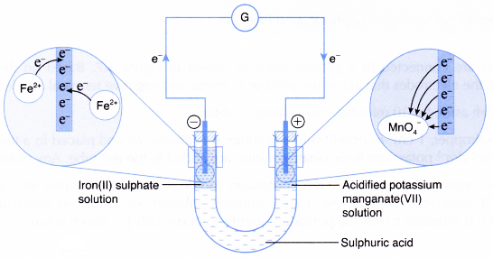
(a) Iron(II) ions act as the reducing agent, releasing electrons to become iron(III) ions. Thus, iron(II) sulphate solution changes colour from pale green to yellow.
![]()
(b) The electrons accumulate at the carbon electrode in the iron(II) sulphate solution and flow out to the connecting wires. This carbon electrode acts as the negative terminal.
(c) The electrons then flow to the positive terminal, which is the carbon electrode in the acidified potassium manganate(VII) solution.
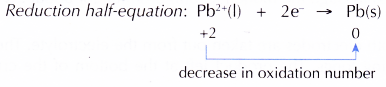
(d) Manganate(VII) ions act as the oxidising agent, accepting the electrons and therefore, undergoing reduction to become colourless manganese(II) ions.
![]()
(e) The overall ionic equation is as follows:
![]()
2. Potassium iodide solution and acidified potassium dichromate(VI) solution
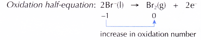
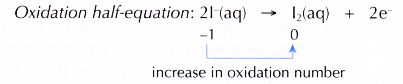
(a) Iodide ions act as the reducing agent, releasing electrons to become iodine molecules. Thus, the colourless potassium iodide solution turns brown.
![]()
(b) The electrons accumulate at the carbon electrode in the potassium iodide solution and flow out to the connecting wires. This carbon electrode acts as the negative terminal.
(c) The electrons then flow to the positive terminal, which is the carbon electrode in the acidified potassium dichromate(VI) solution.
(d) Dichromate(VI) ions act as the oxidising agent, accepting the electrons and therefore, undergoing reduction to become chromium(III) ions.
![]()
(e) The overall ionic equation is as follows:
![]()
3. The continuous flow of electrons from the reducing agent at the negative terminal to the oxidising agent at the positive terminal produces an electric current that causes the indicator of the galvanometer to deflect.
4. Sulphuric acid has two functions:
(a) To separate the reducing agent from the oxidising agent
(b) To complete the circuit by .allowing the transfer of ions to occur
5. Other electrolytes such as potassium nitrate solution and sodium chloride solution can be used in place of sulphuric acid. The electrolyte should not react with either the reducing agent or the oxidising agent used.
6. There are few other pairs of reducing agent and oxidising agent that can be used in this activity. Here are some examples:
Conclusion:
The transfer of electrons occurs from the reducing agent to the oxidising agent through the connecting wires.