How can a transistor be used as a switch?
Transistor as an Automatic Switch: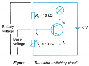
- In a transistor switching circuit as shown in Figure, a fixed resistor, R1 and a variable resistor, R2 form a potential divider.
- By varying the value of the variable resistor, the voltage applied to the base terminal can be adjusted to switch the transistor on or off.
- If the variable resistor is set to zero resistance, the base voltage is zero and the transistor remains switched off. However, if the resistance of the variable resistor is increased, the base voltage increases.
- When the base voltage reaches a certain minimum value, the base current Ib turns the transistor on and it starts conducting. The large collector current Ic passes through the transistor and causes the bulb to light up.
- If the variable resistor in the transistor switching circuit as shown in Figure is replaced by devices such as a light-dependent resistor (LDR), a thermistor or a microphone, the transistor can be used as an automatic switch controlled by light, heat or sound.
People also ask
- What is the use of transistor in electronics?
- What is the basic function of a transistor?
- How does a transistor works as an amplifier?
- Understanding Semiconductor Diodes
- What is doping in a semiconductor?
- What do you mean by rectification?
- What is a half wave rectifier?
- What is a full wave rectifier used for?
- What is meant by smoothing capacitor?
- What do you mean by logic gates?
- What is meant by combinational logic circuits?
Light-controlled Switch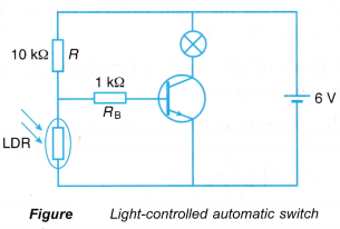
- Figure shows a transistor-based circuit that functions as a light-controlled automatic switch.
- The LDR has a very high resistance in darkness and a low resistance in bright daylight. R is a fixed resistor. The LDR and R form a potential divider in the circuit.
- In daylight, the LDR has a very low resistance as compared to R. Therefore the potential difference across the base of the transistor is too low to switch the transistor on.
- In darkness, the resistance of the LDR is very large and the potential difference across the LDR is high enough to switch the transistor on to light up the bulb. This shows that the transistor- based circuit in Figure switches on the bulb at night and switches off the bulb at daytime automatically.
Heat-controlled Switch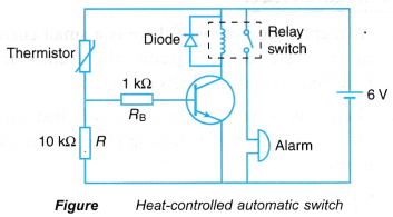
- The circuit in Figure shows a transistor- based circuit that functions as a heat-controlled automatic switch or a high-temperature alarm.
- A thermistor is a special type of resistor in which its resistance changes as the temperature changes. The resistance of a thermistor falls as the temperature rises.
- The thermistor and the resistor R in Figure form a potential divider across the 6 V supply.
- At room temperature, the thermistor has a high resistance as compared to R. Therefore, the potential difference across the base of the transistor is too low and not enough to switch the transistor on.
- When the temperature rises, the resistance of the thermistor falls significantly as compared to R. A large fraction of the voltage of the 6 V supply is dropped across R, increasing the base voltage, Vb. The transistor is switched on and the collector current, Ic flows through the relay coil and then the relay switch is closed.
- The alarm is activated when the relay is switched on.
- The heat-controlled automatic switch is suitable to be used in the fire alarm system.
- The diode in the heat-controlled circuit is to protect the transistor from being damaged by the large induced e.m.f. in the relay coil when the collector current, Ic drops to zero.
Sound-controlled Switch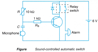
- The circuit in Figure shows a transistor based circuit that functions as a sound-controlled automatic switch or a sound-operated intruder alarm.
- The variable resistor, R is adjusted so that the transistor will only switch on when the microphone has detected a sound.
- The function of the capacitor, C is to prevent the d.c. from the battery from flowing through the microphone (if no sound is detected) which upsets the operation of the transistor. The capacitor, C will only allow the a.c. signal detected by the microphone to flow through the base terminal.