What is meant by combinational logic circuits?
Combinational Logic Circuits using Logic Gates:
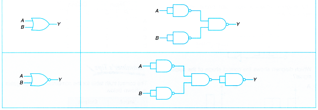
- Some logic operations may require more than one logic gate. Different combinations of gates are designed for different operations. The behaviour of the combined logic gates can be determined by constructing a truth table of the combined gates.
- Figure shows a combination of logic gates circuit which is made up of a combination of AND, OR and NOT gates.
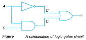
- To construct the truth table, the intermediate inputs, C and D need to be determined first. The output at C is an inverted version of the input A. The output at D obeys the truth table of AND gate.
- Before you can build a truth table for a combination of logic gates, it is important to know the operation of each individual gate in the circuit, as shown in Figure.
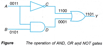 (a) The intermediate outputs C and D are determined first by considering the inputs at A and B as they undergo NOT and AND operations respectively.
(b) The final output Y is determined by considering the inputs at C and D as they undergo OR operation. - The truth table is as shown in Table. From the truth table, the function of this combination of logic gates can then be determined.
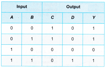
- The function of this logic circuit is ‘high’ when input A is ‘low’ OR input A AND input B is ‘high’.
- In terms of Boolean algebra, the function of the combination of logic gates circuit can also be written as:

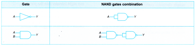
- Combination of NAND gates and combination of NOR gates can create any type of gate. Therefore a logic circuit can be built from just one type of these gates, either NAND gate or NOR gate.
- However, AND gate and OR gate cannot create other gates because they do not have the inverting function.
Table shows the combination of NAND gates to Create the other four basic logic gates.
People also ask
- What do you mean by logic gates?
- Understanding Semiconductor Diodes
- How does a transistor works as an amplifier?
- How can a transistor be used as a switch?
Logic Gate Control Systems
- Most of the electronic control systems consist of three parts as shown in Figure.
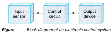 (a) The input sensor is used to detect any changes in physical conditions.
(b) The control circuit is a logic gate circuit that is used to make decision.
(c) The output device can be any indicator. - Figure shows the block diagram of a simple electronic control system that is used as an automatic and manual switch to switch on the street lights when it is dark.
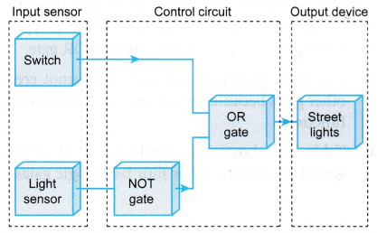 The control system allows the street lights to either be switched on manually by a switch at any time, or automatically by a light sensor when it is dark. The block diagram in Figure shows this function since the output of OR gates is 1 when either or both of its inputs are 1.
 - A security system as shown in Figure is another example.
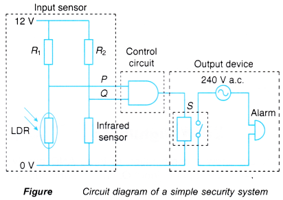
- In this security system, the LDR and the infrared sensor are the input sensors.
- The AND gate is the control circuit while the output device is the alarm.
- The function of this security system is to detect any night intruder into the premises.
- When an intruder crosses the infrared beam at night, the infrared sensor from the input sensor will send a signal to a logic gate in the control circuit which then triggers the alarm.