Selina Concise Physics Class 10 ICSE Solutions Current Electricity
APlusTopper.com provides step by step solutions for Selina Concise ICSE Solutions for Class 10 Physics Chapter 8 Current Electricity. You can download the Selina Concise Physics ICSE Solutions for Class 10 with Free PDF download option. Selina Publishers Concise Physics for Class 10 ICSE Solutions all questions are solved and explained by expert teachers as per ICSE board guidelines.
Download Formulae Handbook For ICSE Class 9 and 10
ICSE SolutionsSelina ICSE Solutions
Selina ICSE Solutions for Class 10 Physics Chapter 8 Current Electricity
Exercise 8(A)
Solution 1.
Current is defined as the rate of flow of charge.
I=Q/t
Its S.I. unit is Ampere.
Solution 2.
Electric potential at a point is defined as the amount of work done in bringing a unit positive charge from infinity to that point. Its unit is the volt.
Solution 3.
The potential difference between two points is equal to the work done in moving a unit positive charge from one point to the other.
It’s S.I. unit is Volt.
Solution 4.
One volt is the potential difference between two points in an electric circuit when 1 joule of work is done to move charge of 1 coulomb from one point to other.
Solution 7.
In a metal, the charges responsible for the flow of current are the free electrons. The direction of flow of current is conventionally taken opposite to the direction of motion of electrons.
Solution 8.
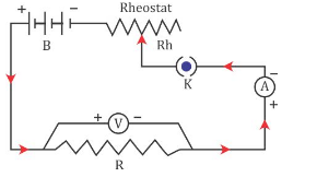
It states that electric current flowing through a metallic wire is directly proportional to the potential difference V across its ends provided its temperature remains the same. This is called Ohm’s law.
V = IR
Solution 11.
Solution 12.
Ohmic Resistor: An ohmic resistor is a resistor that obeys Ohm’s law. For example: all metallic conductors (such as silver, aluminium, copper, iron etc.)
Solution 13.
Solution 14.
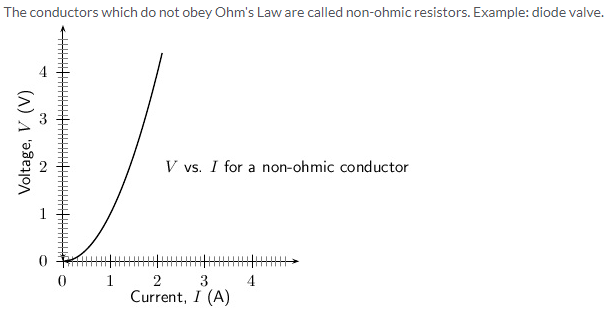
- Ohmic resistor obeys ohm’s law i.e., V/I is constant for all values of V or I; whereas Non-ohmic resistor does not obey ohm’s law i.e., V/I is not same for all values of V or I.
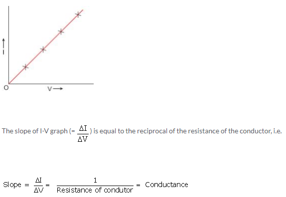
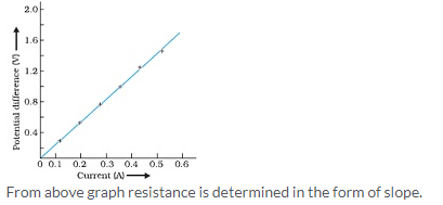
- In Ohmic resistor, V-I graph is linear in nature whereas in non-ohmic resistor, V-I graph is non-linear in nature.
Solution 16.
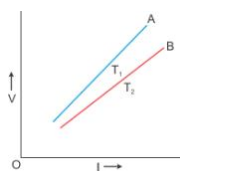
In the above graph, T1 > T2. The straight line A is steeper than the line B, which leads us to conclude that the resistance of conductor is more at high temperature T1 than at low temperature T2. Thus, we can say that resistance of a conductor increases with the increase in temperature.
Solution 17.
Solution 18.
Resistance of a wire is directly proportional to the length of the wire.
R ∝ l
The resistance of a conductor depends on the number of collisions which the electrons suffer with the fixed positive ions while moving from one end to the other end of the conductor. Obviously the number of collisions will be more in a longer conductor as compared to a shorter conductor. Therefore, a longer conductor offers more resistance.
Solution 19.
With the increase in temperature of conductor, both the random motion of electrons and the amplitude of vibration of fixed positive ions increase. As a result, the number of collisions increases. Hence, the resistance of a conductor increases with the increase in its temperature.
The resistance of filament of a bulb is more when it is glowing (i.e., when it is at a high temperature) as compared to when it is not glowing (i.e., when it is cold).
Solution 20.
Iron wire will have more resistance than copper wire of the same length and same radius because resistivity of iron is more than that of copper.
Solution 21.
- Resistance of a wire is directly proportional to the length of the wire means with the increase in length resistance also increases.
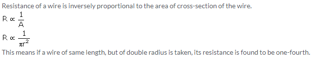
R ∝ l - Resistance of a wire is inversely proportional to the area of cross-section of the wire. If area of cross-section of the wire is more, then resistance will be less and vice versa.
R ∝ 1/A - Resistance increases with the increase in temperature since with increase in temperature the number of collisions increases.
- Resistance depends on the nature of conductor because different substances have different concentration of free electrons.Substances such as silver, copper etc. offer less resistance and are called good conductors; but substances such as rubber, glass etc. offer very high resistance and are called insulators.
Solution 22.
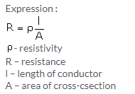
The resistivity of a material is the resistance of a wire of that material of unit length and unit area of cross-section.
Its S.I. unit is ohm metre.
Solution 23.
Solution 24.
Metal < Semiconductor < Insulator
Solution 26.
Manganin
Solution 28.
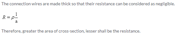
‘Copper or Aluminium’ is used as a material for making connection wires because the resistivity of these materials is very small, and thus, wires made of these materials possess negligible resistance.
Solution 30.
Manganin is used for making the standard resistor because its resistivity is quite large and the effect of change in temperature on their resistance is negligible.
Solution 31.
Generally fuse wire is made of an alloy of lead and tin because its resistivity is high and melting point is low.
Solution 32.
A wire made of tungsten is used for filament of electric bulb because it has a high melting point and high resistivity.
A nichrome wire is used as a heating element for a room heater because the resistivity of nichrome is high and increase in its value with increase in temperature is high.
Solution 33.
A superconductor is a substance of zero resistance at a very low temperature. Example: Mercury at 4.2 K.
Solution 34.
Superconductor
Solution 1 (MCQ).
Nichrome is an ohmic resistance.
Hint: Substances that obey Ohm’s law are called Ohmic resistors.
Solution 2 (MCQ).
For carbon, resistance decreases with increase in temperature.
Hint: For semiconductors such as carbon and silicon, the resistance and resistivity decreases with the increase in temperature.
Numericals
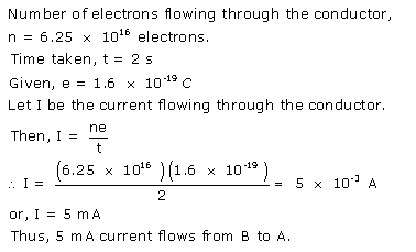
Solution 1.
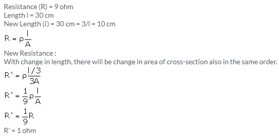
Solution 9.

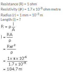
Solution 11.
Solution 12.
Exercise 8(B)
Solution 1.
e.m.f.: When no current is drawn from a cell, the potential difference between the terminals of the cell is called its electro-motive force (or e.m.f.).
Terminal voltage: When current is drawn from a cell, the potential difference between the electrodes of the cell is called its terminal voltage.
Internal Resistance: The resistance offered by the electrolyte inside the cell to the flow of electric current through it is called the internal resistance of the cell.
Solution 2.
| e.m.f. of cell | Terminal voltage of cell |
| 1. It is measured by the amount of work done in moving a unit positive charge in the complete circuit inside and outside the cell. | 1. It is measured by the amount of work done in moving a unit positive charge in the circuit outside the cell. |
| 2. It is the characteristic of the cell i.e., it does not depend on the amount of current drawn from the cell | 2. It depends on the amount of current drawn from the cell. More the current is drawn from the cell, less is the terminal voltage. |
| 3. It is equal to the terminal voltage when cell is not in use, while greater than the terminal voltage when cell is in use. | 3. It is equal to the emf of cell when cell is not in use, while less than the emf when cell is in use. |
Solution 3.
Internal resistance of a cell depends upon the following factors:
- The surface area of the electrodes: Larger the surface area of the electrodes, less is the internal resistance.
- The distance between the electrodes: More the distance between the electrodes, greater is the internal resistance.
Solution 4.
Solution 5.
(a) Terminal voltage is less than the emf : Terminal Voltage < e.m.f.
(b) e.m.f. is equal to the terminal voltage when no current is drawn.
Solution 6.
When the electric cell is in a closed circuit the current flows through the circuit. There is a fall of potential across the internal resistance of the cell. So, the p.d. across the terminals in a closed circuit is less than the p.d. across the terminals in an open circuit by an amount equal to the potential drop across the internal resistance of the cell.
Solution 7.
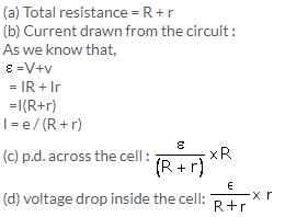
Solution 8.
Solution 9.
Solution 10.
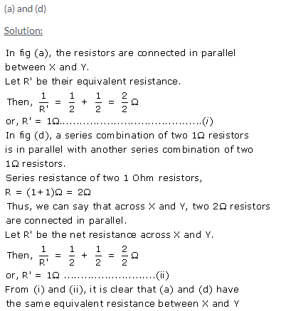
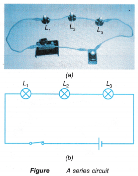
(a) series
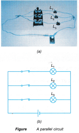
(b) parallel
(c) parallel
(d) series
Solution 11.
For the same change in I, change in V is less for the straight line A than for the straight line B (i.e., the straight line A is less steeper than B), so the straight line A represents small resistance, while the straight line B represents more resistance. In parallel combination, the resistance decreases while in series combination, the resistance increases. So A represents the parallel combination.
Solution 1 (MCQ).
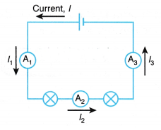
In series combination of resistances, current is same in each resistance.
Hint: In a series combination, the current has a single path for its flow. Hence, the same current passes through each resistor.
Solution 2 (MCQ).
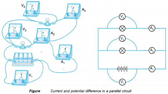
In parallel combination of resistances, P.D. is same across each resistance.
Hint: In parallel combination, the ends of each resistor are connected to the ends of the same source of potential. Thus, the potential difference across each resistance is same and is equal to the potential difference across the terminals of the source (or battery).
Solution 3 (MCQ).
Numericals
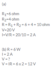
Solution 1.
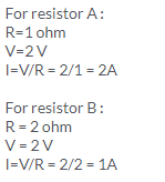
Solution 2.
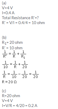
Solution 3.
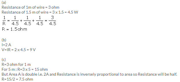
Solution 4.
Solution 5.
Solution 6.
Solution 7.
Solution 8.
Solution 9.
Solution 10.
Solution 11.
Solution 12.
Solution 13.
Solution 14.
Solution 15.
Solution 16.
Solution 17.
Solution 18.
Solution 19.
Solution 20.
Solution 21.
Solution 23.
Solution 24.
Solution 25.
Solution 26.
Solution 27.
Solution 28.
Solution 29.
Solution 30.
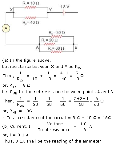
Exercise 8(C)
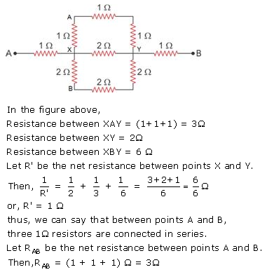
Solution 1.
![]()
Solution 2.
Solution 3.
Solution 4.
The S.I. unit of electrical energy is joule.
1Wh = 3600 J
Solution 5.
The power of an appliance is 100 W. It means that 100 J of electrical energy is consumed by the appliance in 1 second.
Solution 6.
The S.I. unit of electrical power is Watt.
Solution 7.
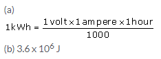
(i) The household unit of electricity is kilowatt-hour (kWh).
One kilowatt-hour (kWh) is the electrical energy consumed by an electrical appliance of power 1 kW when it is used for one hour.
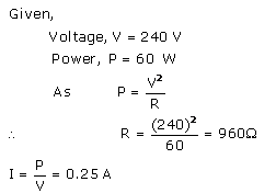
(ii) The voltage of the electricity that is generally supplied to a house is 220 Volt.
Solution 8.
(i) Electrical power is measured in kW and
(ii) Electrical energy is measured in kWh.
Solution 9.
One kilowatt-hour (kWh) is the electrical energy consumed by an electrical appliance of power 1 kW when it is used for one hour.
Its value in SI unit is 1kWh = 3.6 x 10⁶J
Solution 10.
Kilowatt is the unit of electrical power whereas kilowatt-hour is the unit of electrical energy.
Solution 11.
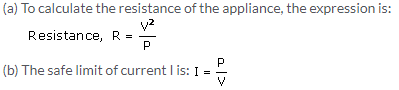
Solution 12.
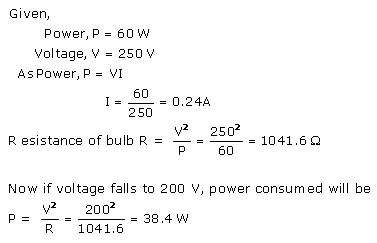
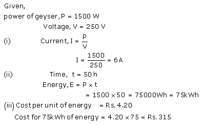
An electrical appliance such as electric bulb, geyser etc. is rated with power (P) and voltage (V) which is known as its power rating. For example: If an electric bulb is rated as 50W-220V, it means that when the bulb is lighted on a 220 V supply, it consumes 50 W electrical power.
Solution 13.
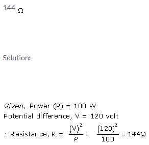
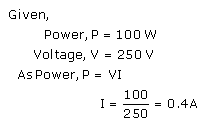
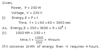
It means that if the bulb is lighted on a 250 V supply, it consumes 100 W electrical power (which means 100J of electrical energy is converted in the filament of bulb into the light and heat energy in 1 second).
Solution 14.
Solution 15.
Solution 16.
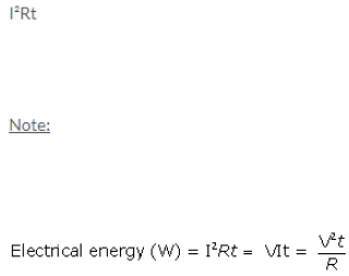
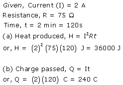
When current is passed in a wire, the heat produced in it depends on the three factors:
- on the amount of current passing through the wire,
- on the resistance of wire and
- on the time for which current is passed in the wire.
- Dependence of heat produced on the current in wire: The amount of heat H produced in the wire is directly proportional to the square of current I passing through the wire, i.e., H ∝ I2
- Dependence of heat produced on the resistance of wire: The amount of heat H produced in the wire is directly proportional to the resistance R of the wire, i.e., H ∝ R
- Dependence of heat produced on the time: The amount of heat H produced in the wire is directly proportional to the time t for which current is passed in the wire, i.e., H ∝ t
Solution 1 (MCQ).
Solution 2 (MCQ).
Numericals
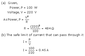
Solution 1.
Solution 2.
Solution 3.
Solution 4.
Solution 5.
Solution 6.
Solution 7.
Solution 8.
Solution 9.
Solution 10.
When one lamp is connected across the mains, it draws 0.25 A current, while if two lamps are connected in series across the mains, current through each bulb becomes
![]()
(i.e., current is halved), hence heating (= I2Rt) in each bulb becomes one-fourth, so each bulb appears less bright.
Solution 11.
Solution 12.
Solution 13.
Solution 14.
Solution 15.
Solution 16.
Solution 17.
Solution 18.
Solution 19.
Solution 20.
More Resources for Selina Concise Class 10 ICSE Solutions
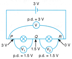
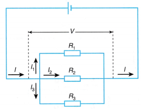
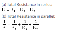
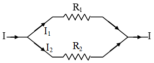 When such a combination of resistance is connected to a battery, all the resistances have the same potential difference across their ends.
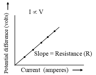
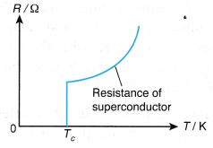
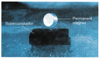
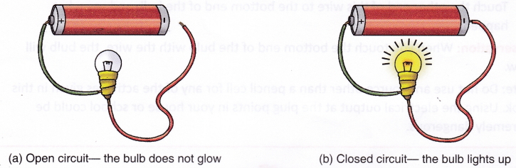
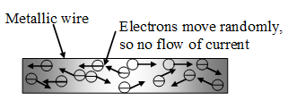 Fig. Flow of electrons inside a metal wire when no potential is applied across its ends
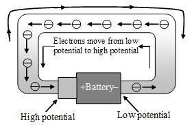 Fig. Flow of electrons inside a metal wire when the two ends of a wire are connected to the two terminals of a battery