What is the definition of resistance in physics?
What is Resistance of a Conductor
The movement of electron gives rise to the flow of current through metals. The moving electrons collide with each other as well as with the positive ions present in the metallic conductor. These collisions tend to slow down the speed of the electrons and hence oppose the flow of electric current.
The property of a conductor by virtue of which it opposes the flow of electric current through it is called its resistance.
- The measure of a conductor’s opposition to current flow is known as the resistance of the conductor. Different conductors have different resistance to current flow.
- Resistance is denoted by the letter R.
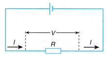
- The resistance, R of a conductor is defined as the ratio of potential difference, V across the conductor to the current, I flowing through it.
Thus:
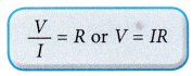
- The SI unit of resistance is ohm. The ohm is denoted by the Greek letter (Ω) called omega.
- Resistance is a scalar quantity.
- One ohm is the resistance of a conductor when a potential difference of 1 volt applied across its ends causes a current of 1 ampere to flow through it.
People also ask
What are the factors that affect the resistance of a conductor?
- In the telecommunications and power industries, it is essential to select suitable electric cables to carry electric currents for many different purposes.
- The most important factor to be considered when selecting the cables is the resistance of the conductors in the cable.
- The resistance of a conductor is affected by the type of material it is made of and by its length, thickness and temperature.
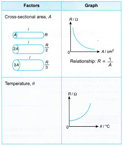
Factors on which resistance of conductor depends
- Effect of the length on the resistance of a conductor
The resistance of a conductor is directly proportional to the length. That is Resistance of a conductor ∝ Length of the conductor. - Effect of the area of cross-section on the resistance of a conductor
The resistance of a conductor is inversely proportional to its area of cross-section.
That is, Resistance of a conductor;
\(R\propto \frac{\text{1}}{\text{Area}\,\text{of}\,\text{cross-section}\,\text{(a)}\,\text{of}\,\text{the}\,\text{conductor}}\)
If the area of cross-section of the conductor is doubled, its resistance gets halved. - Effect of temperature on the resistance of a conductor
The resistance of all pure metals increases with a rise in temperature. The resistance of alloys increases very slightly with a rise in temperature. For metal when temperature increases resistance increases and for semiconductors when temperature increases resistance decreases. - Effect of the nature of material on the resistance of a conductor
Some materials have low resistance, whereas some others have much higher resistance. In general, an alloy has higher resistance than pure metals which from the alloy.
* Copper, silver, aluminium etc., have very low resistance.
* Nichrome, constantan etc., have higher resistance. Nichrome is used for making heating elements of heaters, toasters, electric iron etc.
Thus the resistance, R of a given conductor:
- Is directly proportional to its length, l (R∝ l)
- Is inversely proportional to its cross-sectional area, A (R ∝ 1/A)
- Depends on the type of material or the resistivity, ρ
- Is affected by temperature
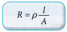
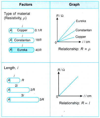
Table summarises the factors affecting resistance and their relationships.
Factors Affecting Resistance of a Wire Experiment
Aim: To investigate the factors affecting resistance.
Problem: What are the factors affecting the resistance of a conducting wire?
Materials: 50 cm eureka wire (s.w.g. 24), 50 cm constantan wire (s.w.g. 24, s.w.g. 30, s.w.g. 34), 50 cm copper wire (s.w.g. 24), 100 cm constantan wire (s.w.g. 24)
Apparatus: Ammeter (0 – 1 A), voltmeter (0 – 5 V), battery holder, rheostat (0 – 15 Ω), switch, connecting wires, three 1.5 V dry cells
A. How does the Type of Material Affect Resistance Experiment
Hypothesis: For a fixed length and thickness of a conducting wire used, its resistance is affected by the type of material.
Variables:
(a) Manipulated variable: Types of material of the wire
(b) Responding variable: Resistance, R
(c) Fixed variable: Thickness, length and temperature of wire
Operational Definition: The resistance, R of a conducting wire is given by the ratio of the reading of the voltmeter to the reading of the ammeter.
Method:
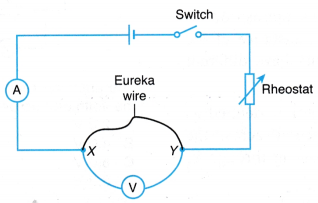
- The electrical circuit as shown in Figure is set up.
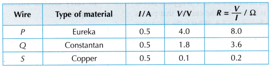
- Wire P (50 cm eureka wire with s.w.g. 24) is connected across terminals X and Y.
- The switch is closed and the rheostat is adjusted to fix the ammeter reading for the current, I = 0.5 A. The reading of the voltmeter for potential difference, V is recorded in a table.
- The value of the resistance, R = V/I is calculated.
- Steps 2 to 4 are repeated by replacing wire P with:
(a) Wire Q: 50 cm constantan wire with s.w.g. 24
(b) Wire 5: 50 cm copper wire with s.w.g. 24
Results:
 Conclusions:
- The resistance, R of the eureka wire is the highest whereas the resistance, R of the copper wire is the lowest.
- The measure of a material’s ability to oppose current flow is also known as the resistivity, p of the material. Thus we can conclude that for a fixed length and thickness of a wire, the resistance varies with the type of material used in the wire.
B. How does the Length of the Wire Affect Resistance Experiment
Hypothesis: The resistance of a conducting wire increases with its length.
Variables:
(a) Manipulated variable: Length of wire, l
(b) Responding variable: Resistance, R
(c) Fixed variable: Thickness, type of wire and temperature of wire
Operational Definition: The resistance, R of a conductor is given by the ratio of the reading of the voltmeter to the reading of the ammeter.
Method:
- The same electrical circuit as shown in Figure is used.
- The 100 cm long constantan wire with s.w.g. 24 is connected across terminals X and Y.
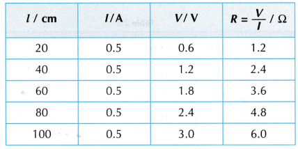
- The length of the wire is adjusted until l = 20 cm.
- The switch is closed and the rheostat is adjusted to fix the ammeter reading for the current, I = 0.5 A. The reading of the voltmeter for potential difference, V is recorded in a table.
- Steps 3 to 4 are repeated for l = 40 cm, 60 cm, 80 cm and 100 cm.
- The value for resistance, R = V/I is calculated for each value of the length of the wire, l.
- The graph of R against l is plotted.
Results:
- Tabulation of results.
- Graph of R against l.

Conclusion:
The resistance, R of a conducting wire is directly proportional to the length of the wire, l. The hypothesis is accepted. The resistance, R of the wire increases with its length, l.
C. How does the Cross Sectional Area (Thickness of Wire) Affect Resistance Experiment
Hypothesis: For a fixed length of a conducting wire, the thicker the wire, the smaller the resistance.
Variables:
(a) Manipulated variable: Thickness of wire
(b) Responding variable: Resistance, R
(c) Fixed variable: Type, length and temperature of wire
Operational Definition:
(a) The thickness of a conductor is determined by the value of its s.w.g.
(b) The resistance, R of a conducting wire is given by the ratio of the reading of the voltmeter to the reading of the ammeter.
Method:
- The same electrical circuit as shown in above Figure is used.
- Wire Q (50 cm long constantan wire with s.w.g. 24) is connected across terminals X and Y.
- The switch is closed and the rheostat is adjusted to fix the ammeter reading for the current, I = 0.5 A. The reading of the voltmeter for potential difference, V is recorded in a table.
- The value of the resistance, R = V/I is calculated.
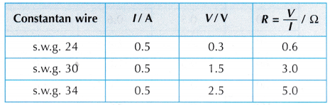
- Steps 2 to 4 are repeated by using 50 cm constantan wires with s.w.g. 30 and s.w.g. 34.
Results:
 Discussion:
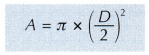
- The value of s.w.g. of a wire corresponds to its diameter. A wire with a larger s.w.g. has a smaller diameter.
- The cross-sectional area, A of a wire can be determined from its diameter, D by the equation:
Conclusion:
The resistance, R of a wire is inversely proportional to its cross-sectional area, A. The thicker the wire, the lower the resistance. The hypothesis is accepted. .
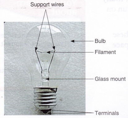
D. How does Temperature Affect Resistance Experiment
Hypothesis: When the temperature of the filament bulb increases, its resistance increases.
Variables:
(a) Manipulated variable: Temperature of the filament
(b) Responding variable: Resistance, R
(c) Fixed variable: Type of bulb used
Operational Definition:
(a) The temperature of the filament is determined by the brightness of the bulb.
(b) The resistance, R of the filament is given by the ratio of the reading of the voltmeter to the reading of the ammeter.
Method:
- The same electrical circuit as shown in above Figure is used with wire P being replaced by a filament bulb.
- The switch is closed and the rheostat is adjusted to maximum so that the bulb does not light up. The readings of the ammeter for current, I and the voltmeter for potential difference, V are recorded in a table.
- Step 2 is repeated by adjusting the rheostat until the bulb is dimly lit, then slightly brighter and very bright.
- The value of the resistance, R = V/I is calculated.
Results: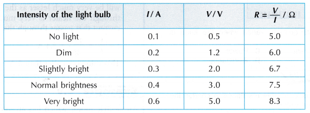
Discussion:
The brightness of the bulb corresponds to the temperature of the bulb. The brighter the bulb, the higher its temperature.
Conclusion:
The resistance of a filament increases as its temperature increases. The hypothesis is accepted.
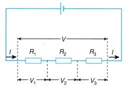
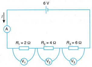
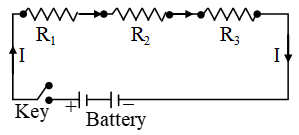 When a series combination of resistances is connected to a battery, the same current (I) flows through each of them.