How series and parallel circuits are different?
Series and Parallel Circuits
Electrical circuit can be connected in two basic ways, in series or in parallel.
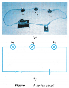
In a series circuit, all the components are connected one after the other in one single path.
- Figure shows a series circuit where three bulbs, L1 , L2 and L3 are connected to a switch and a cell.
- In a parallel circuit, all the components are connected with their corresponding ends joined together at common points to form separate and parallel paths. These paths are called branches.
- Figure shows a parallel circuit, where the three bulbs, L1 , L2 and L3 and their respective switches are connected with their ends joined at two common points before the ends are connected to a cell.
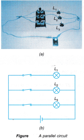
- The brightness of each bulb in a series circuit is equally the same since the same current flows through each bulb.
- The brightness of the bulbs in a parallel circuit is brighter than those in a series circuit with the same number of bulbs.This is because the bulbs in the parallel circuit draw as much current as a single bulb.
- Household wiring circuits operating devices such as a lamp, air conditioner, water heater, fan and washing machine are connected in parallel to the mains supply. Current flow from the mains supply to these circuits are controlled by a fuse box.
- In the fuse box or a consumer unit, a circuit breaker is connected in series to each circuit.
- There is a main switch in the fuse box which is connected in series to the mains supply.
- Therefore, in case of an emergency or repair work, the connection between the mains supply and the household wiring circuits can be broken by turning off the main switch.
People also ask
- How do you calculate the total resistance of a series circuit?
- How do you calculate the total resistance of a parallel circuit?
- What is Electric Current?
- What is an electric field and how is it created?
- What is the Relationship between Electric Current and Potential Difference?
- Electromotive Force, Internal Resistance & Potential Difference of a Cell/Battery
- Relationship between Energy Transferred, Current, Voltage and Time
- Power Rating and Energy Consumption of Various Electrical Appliances
Difference between Series and Parallel Circuits
Table gives the summary of the comparison between a series circuit and a parallel circuit.
| Series circuit | Parallel circuit |
1. Same current at all points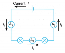 In a series circuit, the current has only one path to flow. The current leaving and returning to the source is not lost. Therefore, in a series circuit, the current is the same at all points, where I = I1 = I2 = I3. | 1. Different current at different paths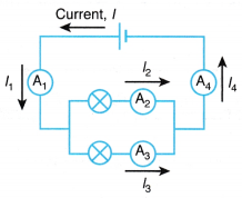 In a parallel circuit, the current has more than one path to flow. The current from the source splits into separate branches. Therefore, in a parallel circuit, the current leaving and returning to the source is the sum of the currents in the separate paths, where I = I1 = I2 + I3 = I4. |
2. Different potential differences at different points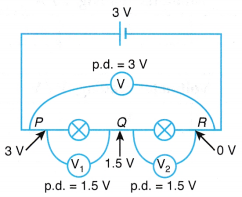 In a series circuit, the potential difference (p.d.) will drop from the highest point (at P, p.d.= 3 V) after crossing each component in the circuit (at Q it drops to 1.5 V and at R it drops to 0 V). The total potential difference across all the components is shared among them. Therefore, in a series circuit, the total potential difference across all the components is the sum of the potential differences across the individual components, V = V1 + V2 | 2. Same potential difference at the same junction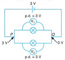 In a parallel circuit, the potential drop across each component in the circuit is the same as they share the same two points, P and Q. The potential difference across a component (3 V) is the potential difference of any other component connected in between. Therefore, the potential difference across the separate branches of a parallel circuit are the same, where V = V1 = V2. |
| 3. When a bulb in a series circuit has blown up, the other bulbs would not be able to light up. | 3. When a bulb in a parallel circuit has blown up, the other bulbs would still be able to light up. |
Application of Series and Parallel Circuits in the Real World
Application of the Principles of Current, Potential Difference and Resistance in Series and Parallel Circuits
- Most of the electric components in our household appliances are connected in parallel circuits. There are some which are connected in combinations of series and parallel circuits.
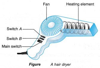
- Figure shows a hairdryer with two switches, A and B.
- Figure shows the circuit diagram of the hairdryer. The fan and the resistor, R are connected in series, while the fan and the heating element are connected in parallel.
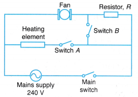
- This is an example of an application of combining series and parallel circuits together.
- When the main switch is closed, the fan is switched on and the air blown out from the hairdryer is cold. Switch A is used to control the heating element. When it is closed, the heating element is turned on and the air blown out is hot.
- The speed of the fan can be controlled by connecting a resistor, R in series with the fan. The speed of the fan is in slow mode when the main switch is closed.
- When switch B is closed, the current bypasses resistor R and flows straight to the fan. This will increase the voltage across the fan and the speed of the fan can be increased.
Series and Parallel Circuits Experiment
Aim: To identify series and parallel circuits.
Materials: Eight bulbs, dry cells, connecting wires
Apparatus: Eight bulb holders, battery holders, five plug-key switches
Method:

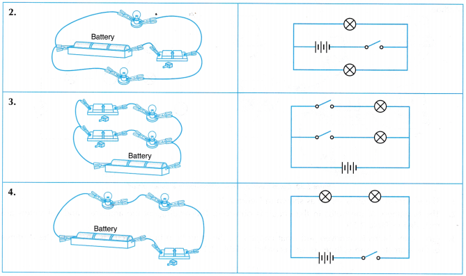
- All the electrical circuits as shown in Table are set up.
- The circuits are switched on and the brightness of the bulbs are observed and compared.
- In each circuit, one of the bulbs is removed and what happens to the other bulb is observed.
Discussion:
- The circuits in 1 and 4 are connected in series. These circuits have only one path for the charges to flow from one terminal to another terminal of the battery.
- The circuits in 2 and 3 are connected in parallel. These circuits have more than one continuous path or branch for the charges to flow from one terminal to another terminal of the battery.
- The bulbs in the parallel circuits light up brighter as compared to the bulbs in the series circuits. The effective resistance in a parallel circuit is much smaller and the current that passes through each bulb is larger.
- When one of the bulbs is removed from a series circuit, the other bulb does not light up. This shows that
e series circuit is broken when one of the bulbs is removed and current cannot continue to pass through the circuit. - When one of the bulbs is removed from a parallel circuit, the other bulb still lights up. This shows that the broken circuit in one branch will not affect the circuit in other branches.
Comparison of Current and Potential Difference in Series and Parallel Circuits Experiment
Aim: To compare the current, I and potential difference, V in series and parallel circuits.
Materials: Two bulbs, dry cells, connecting wires
Apparatus: Two bulb holders, battery holder, three voltmeters, three ammeters
Method:
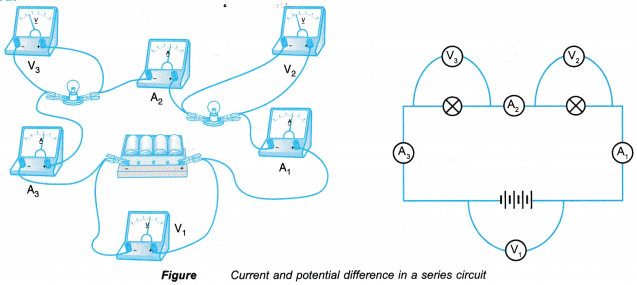
- The electrical circuit is set up as shown in above Figure.
- The brightness of the bulbs in the circuit is observed. The readings of the ammeters and voltmeters are recorded in Table 1.
- One of the bulbs is removed and what happens to the other bulb in the circuit is observed. The readings of the ammeters and voltmeters are recorded in Table 2.
- The bulbs, batteries, ammeters and voltmeters are now connected as shown in Figure.
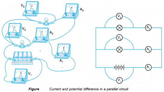
- The brightness of the bulbs is observed. The readings of the ammeters and voltmeters are recorded in Table 1.
- One of the bulbs is removed and what happens to the other bulb is observed. The new readings of the ammeters and voltmeters are recorded in Table 2.
Observation:


Discussion:
- In the series circuit, the current that passes through each bulb is the same. The potential difference across each bulb is also the same as the bulbs are similar. The sum of the potential difference across each bulb is the same as the potential difference across the battery.
- In the parallel circuit, the bulbs are connected parallel to the battery and share the same two points, therefore the potential difference across each bulb is the same as the potential difference across the battery. The total current that flows in the circuit is the sum of the current that passes through each bulb in separate paths.
- In the series circuit, the circuit will break off if one of the bulbs is removed. The ammeter reading is zero as no current passes through it. The potential difference across each bulb is also zero as no current passes through it.
- In the parallel circuit, only the path in which the bulb has been removed will break off. The current can still flow through the other path. The potential difference across the bulb is still the same as the potential difference across the battery.
- The bulbs in the parallel circuit light up brighter as compared to the bulbs in the series circuit. This is because in a parallel circuit, the potential difference across each bulb is very much higher as compared to the potential difference of each bulb in a series circuit. A bulb that lights up brighter indicates that the current that passes through it is larger.
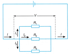
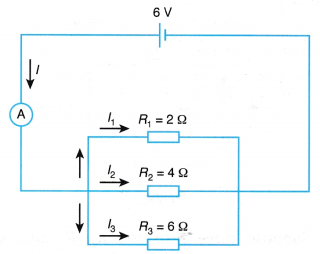
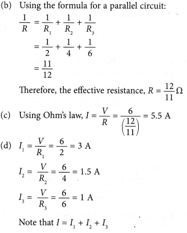
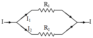 When such a combination of resistance is connected to a battery, all the resistances have the same potential difference across their ends.
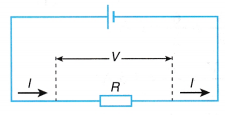
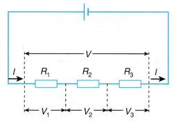
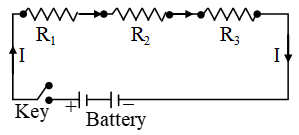 When a series combination of resistances is connected to a battery, the same current (I) flows through each of them.