Plus Two Physics Notes Chapter 4 Moving Charges and Magnetism is part of Plus Two Physics Notes. Here we have given Plus Two Physics Notes Chapter 4 Moving Charges and Magnetism.
| Board | SCERT, Kerala |
| Text Book | NCERT Based |
| Class | Plus Two |
| Subject | Physics Notes |
| Chapter | Chapter 4 |
| Chapter Name | Moving Charges and Magnetism |
| Category | Plus Two Kerala |
Kerala Plus Two Physics Notes Chapter 4 Moving Charges and Magnetism
Introduction; Oersted Experiment
The magnetic effect of current was discovered by Danish Physicist Hans Christians Oersted. He noticed that a current in a straight wire makes a deflection in a magnetic needle.
The deflection increases on increasing current. He also found that reversing the direction of current reverses direction of needle. Oersted concluded that current produces a magnetic field around it.
Magnetic Force
1. Sources and fields:
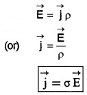
The static charge is the source of electric field. The source of magnetic field is current or moving charge. Both the electric and magnetic fields are vector fields and both obeys superposition principle.
2. Lorentz Force:
The force experienced by moving charge in electric and magnetic field is called Lorentz force. The Lorentz force experienced by charge ‘q’ moving with velocity ‘v’, is given by
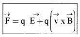
= Felectric + Fmagnetic
The features of Lorentz Force:
- The Lorentz force on positive charge is opposite to that on negative charge because it depends on charge ‘q’.
- The direction of Lorentz force is perpendicular to velocity and magnetic field. Its direction is given by screw rule or right hand rule.
- Only moving charge experiences magnetic force. For static charge (v = 0), magnetic force is zero.
Note:
- A charge particle moving parallel or antiparallel to magnetic field will not experience magnetic force and moves undeviated.
- The work done by magnetic force is zero. Because magnetic force is always perpendicular to direction of velocity.
- A charged particle entering perpendicular magnetic field (θ = 90°) will make a circular path.
- The unit of B is Tesla.
3. Magnetic force on current-carrying conductor:
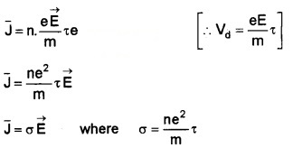
Consider a rod of uniform cross section ‘A’ and length ‘e’. Let ‘n’ be the number of electrons per unit volume (number density). ‘vd’ be the drift velocity of electrons for steady current ‘I’.
Total number of electrons in the entire volume of rod = nAl
Charge of total electrons = nA l.e
‘e’ is the charge of a single electron.
The Lorentz force on electrons,

(I = neAVd)
Motion In Magnetic Field
Case I:
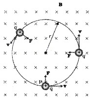
The charged particle enters perpendicular to magnetic field.(\(\overrightarrow{\mathrm{V}}\) is perpendicular to \(\overrightarrow{\mathrm{B}}\))
When charged particle moves perpendicular to magnetic field, it experiences a magnetic force of magnitude, qVB and the direction of the force is perpendicular to both \(\overrightarrow{\mathrm{B}}\) and \(\overrightarrow{\mathrm{V}}\). This perpendicular magnetic field act as centripetal force and charged particle follows a circular path.
Mathematical explanation:
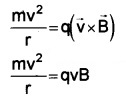
Let a charge ‘q’ enters into a perpendicular magnetic field B with velocity V. Let r be the radius of circular path. The centripetal force for charged particle is provided by magnetic force.
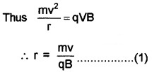
Thus radius of circle described by charged particle depends on momentum, charge and magnetic field. If ω is the angular frequency
ω = \(\frac{v}{r}\)
Thus from (1) we get
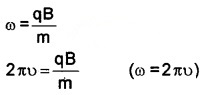
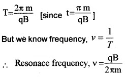
The frequency ν = \(\frac{q B}{2 \pi m}\)
Thus frequency of revolution of charge is independent of velocity (and hence energy)
The time period T = \(\frac{2 \pi \mathrm{m}}{\mathrm{qB}}\)
(ν = \(\frac{1}{T}\)).
Case II:
The charged particles enters at an angle ‘θ’ with magnetic field.
Since the charged particle enters at an angle ‘θ’ with magnetic field, its velocity will have two components; a component parallel to magnetic field, V॥ (Vcosθ) and a component perpendicular to the magnetic field, V⊥(Vsinθ).
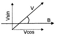
The parallel component of velocity remains unaffected by magnetic field and it causes charged particle to move along the field.
The perpendicular component makes the particle to move in circular path. The effect of linear and circular movement produce helical motion.
Pitch and Helix: The distance moved along magnetic field in one rotation is called pitch ‘P’
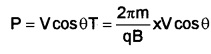
The radius of circular path of motion is called helix.
Motion In Combined Electric And Magnetic Fields
1. Velocity selector:
A transverse electric and magnetic field act as velocity selector. By adjusting value of E and B, it is possible to select charges of particular velocity out of a beam containing charges of different speed.
Explanation:
Consider two mutually perpendicular electric and magnetic fields in a region. A charged particle moving in this region, will experience electric and magnetic force. If net force on charge is zero, then it will move undeflected. The mathematical condition for this undeviation is
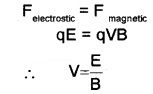
The charges with this velocity pass undeflected through the region of crossed fields.
2. Cyclotron
Uses: It is a device used to accelerate particles to high energy.
Principles: Cyclotron is based on two facts
- An electric field can accelerate a charged particle.
- A perpendicular magnetic field gives the ion a circular path.
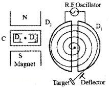
Constructional Details:
Cyclotron consists of two semicircular dees D1 and D2, enclosed in a chamber C. This chamber is placed in between two magnets. An alternating voltage is applied in between D1 and D2. An ion is kept in a vacuum chamber.
Working:
At certain instant, let D1 be positive and D2 be negative. Ion (+ve) will be accelerated towards D2 and describes a semicircular path (inside it). When the particle reaches the gap, D1 becomes negative and D2 becomes positive. So ion is accelerated towards D1 and undergoes a circular motion with larger radius. This process repeats again and again.
Thus ion comes near the edge of the dee with high K.E. This ion can be directed towards the target by a deflecting plate.
Mathematical expression:
Let V be the velocity of ion, q the charge of the ion and B the magnetic flux density. If the ion moves along a semicircular path of radius ‘r’, then we can write
[Since θ =90°, B is perpendicular to v]
or v = \(\frac{q B r}{m}\) _____(1)
Time taken by the ion to complete a semicircular path.
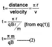
Eq. (2) shows that time is independent of radius and velocity.
Resonance frequency (cyclotron frequency):
The condition for resonance is half the period of the accelerating potential of the oscillator should be ‘t’. (i.e.,T/2 = t or T = 2t). Hence period of AC
T = 2t
K.E of positive ion
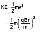
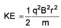
Thus the kinetic energy that can be gained depends on mass of particle charge of particle, magnetic field and radius of cyclotron.
Limitations:
- As the particle gains extremely high velocit, the mass of particle will be changed from its constant value. This will affect the normal working of cyclotron as frequency depends of mass of particle.
- Very small particles like electron can not be accelerated using cyclotron. This is because as the mass of electron is very small the cyclotron frequency required becomes extremely high which is practically difficult.
- Neutron can’t be accelerated
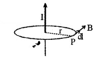
Magnetic Field Due To Current Element; Biot Savart Law
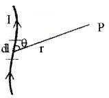
The magnetic field at any point due to an element of current carrying conductor is
- Directly proportional to the strength of the current (I)
- Directly proportional to the length of the element (dl)
- Directly proportional to the sine of the angle (θ) between the element and the line joining the midpoint of the element to the point.
- Inversely proportional to the square of the distance of the point from the element
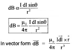
The direction of magnetic field is perpendicularto the plane containing d/and rand is given by right hand screw rule.
In the above expression \(\frac{\mu_{0}}{4 \pi}\) is the constant of proportionality and µ0 is called the permeability of vacuum. Its value is 4π × 10-7 TmA-1.
Note: A magnetic field acting perpendicularly into the plane of the paper is represented by the symbol ⊗ and a magnetic field acting perpendicularly out of the paper is represented by the symbol ⵙ.
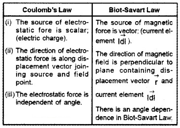
Comparison between Biot-Savart Law and Coulomb’s law
Similarities:
- The two laws are based on inverse square of distance and hence they are long range.
- Both electrostatic and magnetic fields obey superposition principle.
- The source of magnetic field is linear; (the current element \(\overrightarrow{\mathrm{ldl}}\)). The source of electrostatic force is also linear; (the electric charge).
Differences:
Magnetic Field On The Axis Of A Circular Current Loop
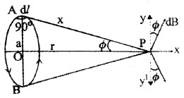
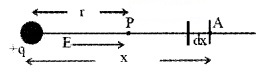
Consider a circular loop of radius ‘a’ and carrying current ‘I’. Let P be a point on the axis of the coil, at distance x from A and r from ‘O’. Consider a small length dl at A. The magnetic field at ‘p’ due to this small element dl,

\(\mathrm{dB}=\frac{\mu_{0} \mathrm{Idl}}{4 \pi \mathrm{x}^{2}}\) _____(1)
[since sin 90° – 1]
The dB can be resolved into dB cosΦ (along Py) and dB sinΦ (along Px).
Similarly consider a small element at B, which produces a magnetic field ‘dB’ at P. If we resolve this magnetic field we get.
dB sinΦ (along px) and dB cosΦ (along py1)
dB cosΦ components cancel each other, because they are in opposite direction. So only dB sinΦ components are found at P, so total filed at P is
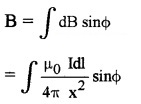
but from ∆AOP we get, sinΦ = a/x
∴ We get
Point at the centre of the loop: When the point is at the centre of the loop, (r = 0)
Then,

1. Magnetic field at the centre of loop:
The magnetic field at a distance x from centre of loop is given by

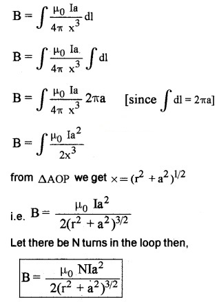
The direction of magnetic field due to current carrying circular loop is given by right hand thumb rule.
Thumb Rule: Curl of palm of right hand around circular coil with fingers pointing in the direction of current. Then extended thumb gives the direction of magnetic field.
Note:
- An anticlockwise current gives a magnetic field out of the coil and a clockwise current gives a magnetic field into the coil.
- The current carrying loop is equivalent to magnetic dipole of dipole moment m = IA
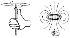
Ampere’s Circuital Law
According to ampere’s law the line integral of magnetic field along any closed path is equal to µ0 times the current passing through the surface.
Applications Of Ampere’s Circuital Law
1. Long straight conductor:
Consider a long straight conductor carrying T ampere current. To find magnetic field at ‘P’, we construct a circle of radius r (passing through P).
According to Ampere’s circuital law we can write

[B and dl are parallel]
B∫dl = µ0I
B2πr = µ0I
B = \(\frac{\mu_{0} I}{2 \pi r}\)
2. Magnetic field due to long solenoid:
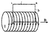
Consider a solenoid having radius T. Let ‘n’ be the number of turns per unit length and I be the current flowing through it.
In order to find the magnetic field (inside the solenoid) consider an Amperian loop PQRS. Let V ‘ be the length and ‘b’ the breadth
Applying Amperes law, we can write
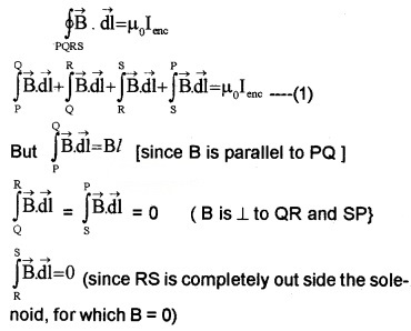
Substituting the above values in eq (1),we get
Bl = µ0 lenc ____(2).
But lenc = n l I
where ‘nl ’ is the total number of turns that carries current I (inside the loop PQRS)
∴ eq (2) can be written as
Bl = µ0 nIl
B = µ0nI
If core of solenoid is filled with a medium of relative permittivity µr. then
B = µ0µrnl
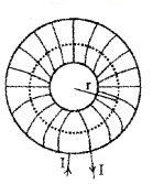
3. The toroid:
Consider a toroid of average radius ‘r’. Let ‘n’ be the number of turns per unit length. Let I be the current flowing through the toroid. In order to find magnetic field inside the toroid, an camperian loop of radius ‘r’ is considered.
Applying Amperes law to the loop, we can write
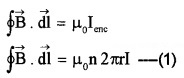
Where ‘n2πr ‘ is the total number of turns of the solenoid that carries current I (inside the Amperian loop) Integrating the eq(1) we get
B 2πr = µ02πrI
B = µ0n I
If the core of the solenoid is filled with a medium of relative permeability µr then the above equation is modified as
![]()
Note: The magnetic field due to toroid is same as that due to solenoid.
Force Between Two Parallel Currents, The Ampere Force Between Two Parallel Conductors
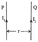
P and Q are two infinitely long conductors placed parallel to each other and separated by a distance r, Let the current through P and Q be l1 and l2 respectively.
Magnetic field at a distance ‘r’ from P is
![]()
Conductor ‘Q’ is placed in this magnetic field.
If l2 is the length of the conductor ‘Q’, the Lorentz force on ‘Q’ is
∴ Force per unit length can be written as,

Where f = \(\frac{F}{\ell_{2}}\)
Note:
- When currents are in the same direction, the force is attractive
- If the currents are in the opposite direction, the force is repulsive.
Definition of ampere:
An ampere is defined as that constant current which if maintained in two straight parallel conductors of infinite lengths placed one meter apart in vacuum will produce between a force of 2 × 10⁻⁷ Newton per meter length.
Force On A Current Loop, Magnetic Dipole
1. Torque on a rectangular current loop in uniform magnetic filed:
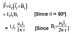
Considers rectangular coil PQRS of N turns which is suspended in a magnetic field, so that it can rotate (about yy 1). Let ‘l’ be the length (PQ) and ‘b’ be the breadth (QR).
When a current l flows in the coil, each side produces a force. The forces on the QR and PS will not produce torque. But the forces on PQ and RS will produce a Torque.
Which can be written as
τ = Force × ⊥ distance _______(1)
But, force = BlI ______(2)
[since θ = 90° ]
And from ∆QTR , we get
⊥ distance (QT) = b sin θ ______(3)
Substituting the vales of eq (2) and eq (3) in eq(1) we get
τ = BIl b sin θ
= BIA sin θ [since lb = A (area)]
τ = IAB sin θ
τ = mB sin θ [since m = IA]
![]()
If there are N turns in the coil, then
τ = NIAB sin θ
2. Circular Current loop as a magnetic dipole:
Current loop of any shape act as magnetic dipole.
Current loop acts as magnetic dipole:
The magnetic field due to circular loop of radius R carrying current I at a distance ‘x’ from the centre of loop (on the axis of loop) is given by,
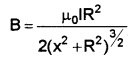
The magnetic field at large distance (x>>R) on axis of loop is

Dividing and multiplying by π
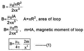
Comparison of magnetic dipole and electric dipole:
The equation (1) is similar to electric field due to electric dipole at a distance ‘x’ from the centre of dipole on its axial line.
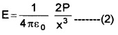
Comparing eq(1) and (2), we get 1
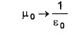
m → P
B → E
From this comparison it is clear that a circular current loop acts as a magnetic dipole.
3. The magnetic dipole moment of a revolving electron:
According to Bohr’s model of atom, electrons are revolving around nucleus in its orbit. The electron revolving in its orbit can be considered as circular current loop.
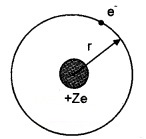
Consider an electron of charge e, revolving around nucleus of charge +ze as shown in figure. The uniform, circular motion of electron constitute current ‘I’. If T is the period of revolution e
I = \(\frac{e}{T}\) _____(1)
If r is the radius of orbit and V s the orbital speed then
T = \(\frac{2 \pi r}{v}\)
Substituting this in (1), we get
I = \(\frac{e v}{2 \pi r}\)
The magnetic moment associated orbiting electron is denoted by µ1
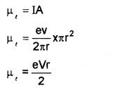
A = πr2, area of orbit
Dividing and multiplying by me (Mass of electron)
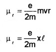
Applying Quantum Theory, Bohr has proposed that angular momentum of electron can take only discrete values given by,
l = \(\frac{\mathrm{nh}}{2 \pi}\) (Bohr’s quantization condition where n = 1, 2, 3, ……..etc) where h is Plank’s constant. Thus
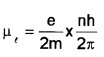
The orbital magnetic moment of electron is given by
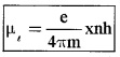
Bohr Magneton: We get the minimum value of magnetic moment, when n = 1 ie
![]()
(when n = 1)
Its value is 9.27 × 10⁻²⁴ Am2. This is called Bohr magneton.
Gyromagnetic Ratio:
The orbital magnetic moment of electron is related to orbital angular momentum ‘l’ as
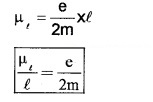
The ratio of orbital magnetic moment to orbital angular momentum is constant. This constant is called gyromagnetic ratio. Its value is 8.8 × 10¹⁰ c/kg for an electron.
The Moving Coil Galvanometer
It is an instrument used to measure small current.
Principle: A conductor carrying current when placed in a magnetic field experiences a force, (given by Fleming’s left hand rule).
Construction:
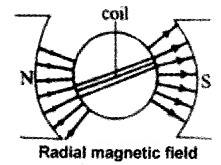
A moving coil galvanometer consists of rectangular coil of wire having area ‘A’ and number of turns ‘n’ which is wound on metallic frame and is placed between two magnets. The magnets are concave in shape, which produces radial field.
Working: Let ‘l’ be the current flowing the coil, Then the torque acting on the coil.
τ = NIAB Where A is the area of coil and B is the magnetic field.
This torque produces a rotation on coil, thus fiber is twisted and angle (Φ). Due to this twisting a restoring torque (τ = KΦ) is produced in spring.
Under equilibrium, we can write
Torque on the coil = restoring torque on the spring
or NIAB = kΦ
or Φ = (\(\frac{\mathrm{BAN}}{\mathrm{K}}\))I
The quantity inside the bracket is constant for a galvanometer.
Φ α I
The above equation shows that the deflection depends on current passing through galvanometer.
1. Ammeter and voltmeter:
For measuring large current, the galvanometer can be converted in to ammeter and voltmeter.
Ammeter:
Ammeter is an instrument used to measure current in the circuit.
A galvanometer can be converted into an ammeter by a low resistance (shunt) connected parallel to it.
Theory:
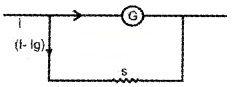
Let G be the resistance of the galvanometer, giving full deflection fora current Ig.
To convert it into an ammeter, a suitable shunt resistance ‘S’ is connected in parallel. In this arrangement Ig current flows through Galvanometer and remaining (I – Ig) current flows through shunt resistance.
Since G and S are parallel
P.d Across G = p.d across
Ig × G = (I – Ig)S

Connecting this shunt resistance across galvanometer we can convert a galvanometer into ammeter.
2. Conversion of galvanometer into voltmeter:
To convert a galvanometer into a voltmeter, a high resistance is connected in series with it.
Theory:
Let Ig be the current flowing through the galvanometer of resistance G. Let R be the high resistance co connected in series with G.
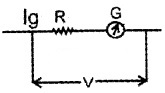
From figure we can write
V = IgR + IgG
V – IgG = IgR
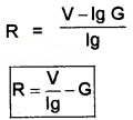
Using this resistance we can covert galvanometer in to voltmeter.
Current sensitivity:
The current sensitivity of galvanometer is the deflection produced by unit current.

The current sensitivity can be increased by increasing number of turns.
The voltage sensitivity:
The voltage sensitivity of galvanometeris the deflection produced by unit voltage.
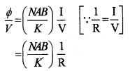
The increase in number of turns will not change voltage sensitivity.
When number of turns double (N → 2N), the resistance of the wire will be double (ie. R → 2R). Hence the voltage sensitivity does not change.
We hope the Plus Two Physics Notes Chapter 4 Moving Charges and Magnetism help you. If you have any query regarding Plus Two Physics Notes Chapter 4 Moving Charges and Magnetism, drop a comment below and we will get back to you at the earliest.