Plus Two Physics Notes Chapter 9 Ray Optics and Optical Instruments is part of Plus Two Physics Notes. Here we have given Plus Two Physics Notes Chapter 9 Ray Optics and Optical Instruments.
| Board | SCERT, Kerala |
| Text Book | NCERT Based |
| Class | Plus Two |
| Subject | Physics Notes |
| Chapter | Chapter 9 |
| Chapter Name | Ray Optics and Optical Instruments |
| Category | Plus Two Kerala |
Kerala Plus Two Physics Notes Chapter 9 Ray Optics and Optical Instruments
Introduction
In this chapter, we consider the phenomena of reflection, refraction and dispersion of light, using the ray picture of light.
Reflection Of Light Byspherical Mirrors
Laws of reflection:
- According to the first law of reflection, the angle of reflection equals the angle of incidence.
- According to the second law of reflection, the incident ray, reflected ray and the normal to the point of incidence all lie in the same plane.
1. Sign convention:
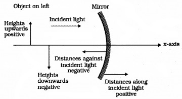
- According to this convention, all distances are measured from the pole of the mirror or the optical centre of the lens.
- The distances measured in the same direction as the incident light are taken as positive and
those measured in the direction opposite to the direction of incident light are taken as negative. - The heights measured upwards are taken as positive. The heights measured downwards are taken as negative.
2. Focal length of spherical mirrors:
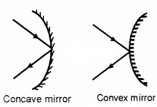
Reflection of light: Spherical mirrors are of two types.
- Concave mirror
- Convex mirror
Principal focus of a concave mirror:
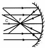
A narrow parallel beam of light, parallel and close to the principal axis, after reflection converges to a fixed point on the principal axis is called principal focus of concave mirror.
Principal focus of a convex mirror:
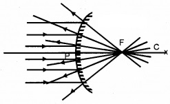
A narrow parallel beam of light, parallel and close to the principal axis, after reflection appears to diverge from a point on the principal axis is called principal focus of convex mirror.
Relation connecting focal length and radius of curvature:
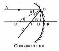
Consider a ray AB parallel to principal axis incident on a concave mirror at point B and is reflected along BF. The line CB is normal to the mirror as shown in the figure.
Let θ be angle of incidence and reflection.
Draw BD ⊥ CP,
In right angled ΔBCD,
Tanθ = \(\frac{B D}{C D}\) _____(1)
In right angled ΔBFD,
Tan2θ = \(\frac{B D}{F D}\) _____(2)
Dividing (1)and(2)
\(\frac{\tan 2 \theta}{\tan \theta}=\frac{C D}{F D}\) ____(3)
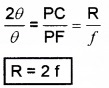
If θ is very small, then tanθ ≈ θ and tan2θ ≈ 2θ
The point B lies very close to P. Hence CD ≈ CP and FD ≈ FP From (3) we get
3. The mirror equation:
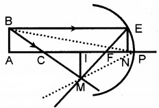
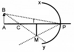
Let points P, F, C be pole, focus, and centre of curvature of a concave mirror. Object AB is placed on the principal axis. A ray from AB incident at E and then reflected through F. Another ray of light from B incident at pole P and then reflected. These two rays meet at M. The ray of light from point B is passed through C. Draw EN perpendicular to the principal axis.
ΔIMF and ΔENF are similar.
ie. \(\frac{I M}{N E}=\frac{I F}{N F}\) _____(1)
but IF = PI – PF and NF = PF (since aperture is small)
hence eq. (1) can be written as
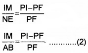
[∵ NE = AB)
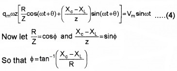
ΔABP and ΔIMP are similar
![]()
From eq.(2) and eq.(3), we get

applying sign convention we get
PI = -v
PF = -F
PA = -u
Substituting these values in eq.(4) we get
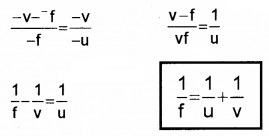
This is called mirror formula or mirror equation.
Linear magnification:
Linear magnification is defined as the ratio of the height of the image to the height of the object.
Consider an object AB having height ho, which produces an image IM having height hi
In the figure, ΔABP and ΔIMP are equal. ie.
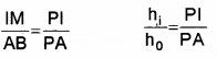
Applying sign convention
PI = -V, PA = -u, hi = -ve and ho = +ve
We get
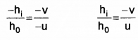
But we know \(\frac{h_{i}}{h_{0}}\) = m (magnification) ie.

This formulae is true fora concave mirror and convex mirror.
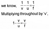
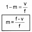
Relation connecting v, f, and m
We have
\(\frac{1}{u}+\frac{1}{v}=\frac{1}{f}\)
Multiplying throughout by ‘v’, we get
\(\frac{v}{u}+\frac{v}{v}=\frac{v}{f}\)
But m = -v/u
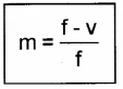
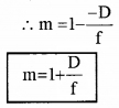
ie. -m + 1 = \(\frac{v}{f}\)
m = 1 – \(\frac{v}{f}\)
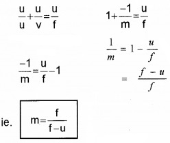
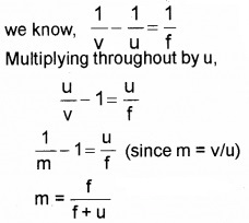
Relation connecting u, f and m
We know
\(\frac{1}{u}+\frac{1}{v}=\frac{1}{f}\)
Multiplying throughout by ‘u’ we get
Refraction
The phenomenon of bending of light when it travels from one medium to another is known as refraction.
Light from rarer to denser medium:
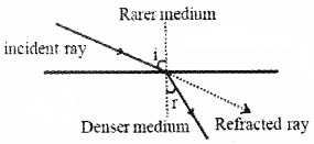
When light travels from a rarer medium to a denser medium, it deviates towards the normal.
Light from denser to rarer medium:
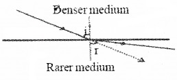
When light travels from a denser medium to a rarer medium, it deviates away from the normal.
Laws of refraction:
First law:
The incident ray, the refracted ray, and the normal at the point of incidence are all in the same plane.
Second law (Snell’s law):
The ratio of the sine of the angle of incidence to the sine of the angle of refraction is a constant for a given pair of media and for the given colour of light used. This constant is known as the refractive index of second medium w.r. t. the first medium.
Explanation:
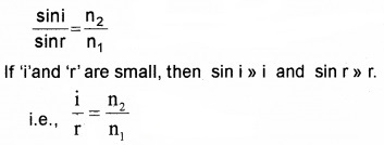
If ‘i’ is the angle of incidence in the first medium and ‘r’ is the angle of refraction in the second medium, then by Snell’s law,
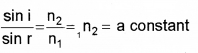
Where 1n2 is the refractive index of the second medium with respect to the first medium. If the first medium is air, then sini/sinr is known as absolute refractive index of the second medium.
ie, \(\frac{\sin i}{\sin r}=n\)
where ‘n’ is the refractive index of the second medium.
Some examples of refraction:
(a) Apparent depth:
When an object (in a denser medium) is viewed from a rarer medium, it seems to be raised towards the surface. This is called apparent depth.
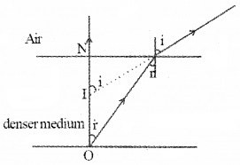
(b) Twinkling of stars:
Twinkling of stars is due to the refraction of star light at different layers of the atmosphere. Due to this refraction the star at S appears at S1. But the density of the layer continuously changes. So, the apparent position continuously changes. Thus the star appears to be twinkling.
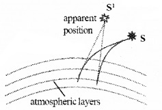
(c) Apparent shift in the position of the sun at sunrise and sunset:
Sun is visible before sunrise and after sunset because of atmospheric refraction. The density of atmospheric air decreases as we go up. So the rays coming from the sun deviates towards the normal. So the sun at ‘S’ appears to come from ‘S1’. Thus an observer on earth can see the sun before sunrise and after sunset.
Total Internal Reflection
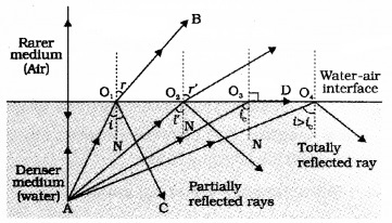
When a ray of light passes from a denser to rarer medium, after refraction the ray bends away from the normal. If the angle of incidence increases, the angle of refraction increases. When the angle of refraction is 90°, the corresponding angle of incidence is called the critical angle.
If we increases the angle of incidence beyond the critical angle, the ray is totally reflected back to the same medium. This phenomenon is called total internal reflection.
Relation between critical angle and refractive index
Refractive index,

where ‘C’ is the critical angle.
A demonstration for total internal reflection
Demonstration – 1:
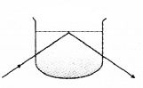
Take a soap solution in a beaker. Now direct the laser beam from one side of the beaker such that it strikes the upper surface of water obliquely. Adjust the direction of laser beam until the beam is totally reflected back to water.
Demonstration – 2:
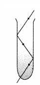
Take a soap solution in a long test tube and shine the laser light from top, as shown in above figure. Adjust the direction of the laser beam such that it is totally internally reflected. This is similar to what happens in optical fibres.
Condition for total internal reflection:
- Light should travel from denser medium to rarer medium.
- Angle of incidence in the denser medium should be greater than the critical angle.
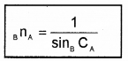
Relative critical angle:
Critical angle of a medium A with respect to a rarer medium B is represented as BCA. BCA is related to the refractive index BnA as
Some Effects And Applications Of Total Internal Reflection
(a) Brilliance of diamond:
Refractive index of diamond is high (n = 2.42) and the critical angle is small (C = 24.41°). More over the faces of the diamond are cut in such a way that a ray of light entering the crystal undergoes multiple total reflections. This multiple reflected light come out through one or two faces. So these faces appear glittering.
(b) Mirage:
On hot summer days the layer of air in contact with the sand becomes hot and rare. The upper layers are comparatively cooler and denser. When light rays travel from denser to rarer, they undergo total internal reflection. Thus image of the distant object is seen inverted. This phenomenon is Known as mirage.
(c) Looming (superior mirage):
Due to the mist and fog in cold countries, distant ship cannot be seen clearly. But due to the total internal reflection, the image of the ship appears hanging in air. This illusion is known as looming.
(d)Total reflection prisms:
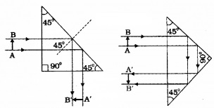
A right-angled prism is called a total reflecting prisms. Total reflecting prisms are based on the principle of total internal reflection. With the help of these prisms, the direction of the incident ray can be changed. The refractive index for glass is 1.5 and its critical angle is 42°. When a ray of light makes an angle of incident more than 42° (within the glass) the ray undergoes total internal reflection.
1. Optical fibres:
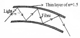
Optical fibres consist of a number of long fibres made of glass or quartz (n = 1.7). They are coated with a layer of a material of lower refractive index (1.5). When light incident on the optical fibre at angle greater than the critical angle, it undergoes total internal reflection. Due to this total internal reflection, a ray of light can travel through a twisted path.
Uses:
- Used as a light pipe in medical and optical diagnosis.
- It can be used for optical signal transmissions.
- Used to carry telephone, television and computer signals as pulses of light.
- Used for the transmission and reception of electrical signals which are converted into light signals.
Refraction At Spherical Surfaces And By Lenses
Spherical lenses:
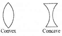
There are two types of lenses
- convex lenses and
- concave lenses.
Principal axis:
A straight line passing through the two centers of curvature is called the principal axis of the lens.
Principal focus (F):
A narrow beam of parallel rays, parallel and close to the principal axis, after refraction, converges to a point on the principal axis in the case of a convex lens or appears to diverge from a point on the axis in the case of a concave lens. This fixed point is called the principal focus of the lens.
Focal length:
It is distance between the optic centre and the principal focus.
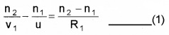
1. Refraction at a spherical surface:
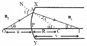
Consider a convex surface XY, which separates two media having refractive indices n1 and n2. Let C be the centre of curvature and P be the pole. Let an object is placed at ‘O’, at a distance ‘u’ from the pole. I is the real image of the object at a distance V from the surface. OA is the incident ray at angle ‘i’ and Al is the refracted ray at an angle ‘r’. OP is the ray incident normally. So it passes without any deviation. From snell’s law,
r1 = n2 _____(1)
From the Δ OAC, exterior angle = sum of the interior opposite angles
i.e., i = α + θ ______(2)
Similarly, from ΔIAC,
a = α + β
r = α – β ______(3)
Substituting the values of eq(2) and eq(3)in eqn.(1) we get,
n1(α + θ) = n2(α – β)
n1α + n1θ = n2α – n2β
n1θ + n2β = n2α – n1α
n1θ + n2β = (n2 – n1)α _______(4)
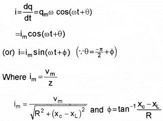
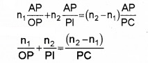
From OAP, we can write,
![]()
From IAP, β = \(\frac{\mathrm{AP}}{\mathrm{PI}}\), From CAP, α = \(\frac{\mathrm{AP}}{\mathrm{PC}}\)
Substituting θ, β and α in equation (4) we get,
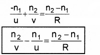
According to New Cartesian sign convection, we can write,
OP = -u, PI = +v and PC = R
Substituting these values, we get
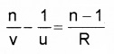
Case -1: If the first medium is air, n1 = 1, and n2 = n,
2. Refraction by a lens:
Lens Maker’s Formula (for a thin lens):
Consider a thin lens of refractive index n2 formed by the spherical surfaces ABC and ADC. Let the lens is kept in a medium of refractive index n1 Let an object ‘O’ is placed in the medium of refractive index n1 Hence the incident ray OM is in the medium of refractive index n1 and the refracted ray MN is in the medium of refractive index n2.
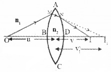
The spherical surface ABC (radius of curvature R1) forms the image at I1. Let ‘u’ be the object distance and ‘v1‘ be the image distance.
Then we can write,
This image I1 will act as the virtual object for the surface ADC and forms the image at v.
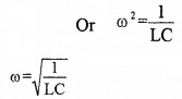
Then we can write,
![]()
Adding eq (1) and eq (2) we get
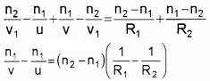
Dividing throughout by n1, we get
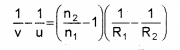
if the lens is kept in air, \(\frac{\mathrm{n}_{2}}{\mathrm{n}_{1}}\) = n
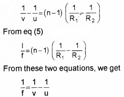
So the above equation can be written as,
![]()
From the definition of the lens, we can take, when u = 8, f = v
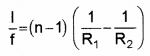
Substituting these values in the eq (3), we get
![]()
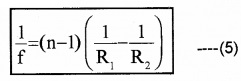
For convex lens,
f = +ve, R1 = +ve, R2 = – ve
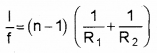
For concave lens,
f = -ve, R1 = -ve, R2 = +ve
Lens formula
Linear magnification: If ho is the height of the object and hi is the height of the image, then linear magnification

3. Power of a lens:
Power of a lens is the reciprocal of focal length expressed in meter.
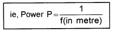
Unit of power is dioptre (D).
4. Combination of thin lenses in contact:
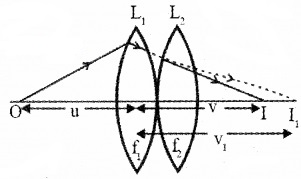
Consider two thin convex lenses of focal lengths f1 and f2 kept in contact. Let O be an object kept at a distance ‘u’ from the first lens L1, I1 is the image formed by the first lens at a distance v1.
Then from the lens formula, we can write,
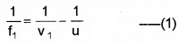
This image will act as the virtual object for the second lens and the final image is formed at I (at a distance v). Then
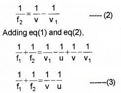
If the two lenses are replaced by a single lens of focal length ‘F’ the image is formed at V. Then we can write,
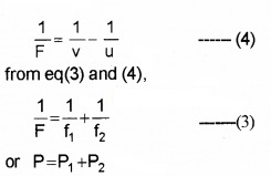
where P is the power of the combination, P1 and P2 are the powers of the individual lenses.
Magnification (combination of lenses):
If m1, m2, m3,…….. are the magnification produced by each lens,
then the net magnification,
m = m1. m2. m3……….
Relation connecting m, u and f:
Relation connecting m,v and f:
Refraction Through A Prism
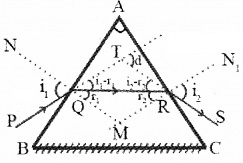
ABC is a section of a prism. AB and AC are the refracting faces, BC is the base of the prism, ∠A is the angle of prism.
Aray PQ incidents on the face AB at an angle i1. QR is the refracted ray inside the prism, which makes two angles r1 and r2 (inside the prism). RS is the emergent ray at angle i2.
The angle between the emergent ray and incident ray is the deviation ‘d’.
In the quadrilateral AQMR,
∠Q + ∠R = 180°
[since and N1M are normal] ie,
∠A + ∠M = 180° ____(1)
In the Δ QMR.
∴ r1 + r2 + ∠M = 180° _____(2)
Comparing eq (1) and eq (2)
r1 + r2 = ∠A ______(3)
From the Δ QRT,
(i1 – r1) + (i2 – r2) = d
[since exterior angle equal sum of the opposite interior angles]
(i1 + i2) – (r1 + r2) = d
but, r1 + r2 =A
∴ (i1 + i2 ) – A = d
(i1 + i2) = d + A _____(4)
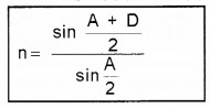
It is found that for a particular angle of incidence, the deviation is found to be minimum value ‘D’.
At the minimum deviation position,
i1 = i2 = i, r1 = r2 = r and d = D
Hence eq (3) can be written as,
r + r= A
or r = \(\frac{A}{2}\) ______(5)
Similarly eq (4) can be written as,
i + i = A + D
i = \(\frac{A+D}{2}\) _____(6)
Let n be the refractive index of the prism, then we can write,
n = \(\frac{\sin i}{\sin r}\) ______(7)
Substituting eq (5) and eq (6) in eq (7),
i – d curve:
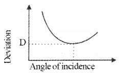
It is found that when the angle of incidence increases deviation (d) decreases and reaches a minimum value and then increases. This minimum value of the angle of deviation is called the angle of minimum deviation.
Dispersion By A Prism
Dispersion: The splitting of the white light into its component colours is called dispersion.
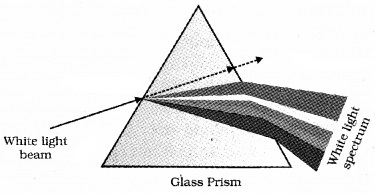
The pattern of colour components of light is called the spectrum of light.
Reason for dispersion:
The refractive index is different for different colours. Refractive index for violet is higher than red. This variation of refractive index of medium with the wavelength causes dispersion.
Some Natural Phenomena Due To Sunlight
1. The rainbow:
The rainbow is an example of the dispersion of sunlight by the water drops in the atmosphere. The conditions for observing a rainbow are that the sun should be shining in one part of the sky while it is raining in the opposite part of the sky.
There are two types rainbow
- Primary rainbow
- secondary rainbow.
(i) Primary rainbow:
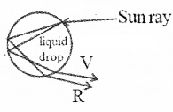
In a primary rainbow, after refraction at the surface of water droplet, the ray suffers one internal reflection and finally comes out of the drop by forming an inverted spectrum. The maximum deviated light is red (42°) and the least deviated light is violet (40°).
(ii) Secondary rainbow:
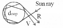
secondary rainbow, after refraction at the surface of water droplet, the ray suffers two total internal reflection and finally comes out of the droplet by forming a spectrum. The most deviated light in this spectrum is violet (53°) and the least deviated light is red (50°).
2. Scattering of light:
When sunlight travels through the earth’s atmosphere, it changes its direction by atmospheric particles. This is called scattering. Light of shorter wavelength is scattered much more than light of longer wavelength. Scattering is possible only when size of the particles is comparable to the wavelength of incident light.
Rayleigh’s scattering law:
The intensity of the scattered light from a molecule is inversely proportional to the 4th power of the wavelength.
ie, \(I \alpha \frac{1}{\lambda^{4}}\)
I – Intensity of Scattering
Blue colour of sky:
According to Rayleigh scattering, scattering is inversely proportional to the fourth power of its wavelength. Hence shorterwavelength is scattered much more than longer wavelength. Thus blue colour is more scattered than the other colours. So sky appears blue.
Whiteness of clouds:
Clouds contain large partides (dust, H2O), which scatter all colours almost equally. Hence clouds appear white.
Colours of the sunset (or sunrise):
At sunrise and sunset light has to travel a longer distance before reaching the earth. During this time, smaller wavelengths are scattered away. The remaining colours is red. Hence sky appears red in colour.
Optical Instruments
Mirrors, lenses and prisms, periscope, Kaleidoscope, Binoculars, telescopes, microscopes are some examples of optical devices Our eye is one of the most important optical device.
1. The eye:
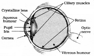
Human eye consists of an eyeball of size 2.5cm in diameter. The very thin skin in front of the eye is known as cornea. Behind cornea, the empty space is known as aqueous humor. The small wall behind cornea is known as iris. In this iris a small circular opening is there, which is known as pupil. Iris can adjust its tension to vary the size of the pupil.
Behind the iris a muscular membrane is there which is known as ciliary muscle. The focal length of the crystalline lens can be adjusted to see the object any separation by adjusting the tension of ciliary muscles. The backwall of eye is known as retina.
It consists of light sensitive cells known as rods and cones. The rods are sensitive to intensity and cones are sensitive to colour. The signals from retina are transferred to the brain by optic nerves.
The brightest point in the retina is known as yellow spot and the lowest point in the eye (retina) is known as blind spot. The space between the lens and retina is filled by a liquid which is known as vitreous humor.
Defects of Vision
a. Myopia or shortsightedness:
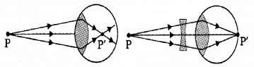
A person suffering from myopia can see only nearby objects but cannot see objects beyond a certain distance clearly. This defect occurs due to
- Elongation of eyeball
- Short focal length of eye lens
It can be corrected by using a concave lens of suitable focal length.
b. Hypermetropia or Far sightedness:
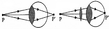
A person suffering from this defect can see only distant object clearly but cannot see nearby objects clearly. This defect occurs due to
- Decrease in the size of the eyeball.
- Increase in focal length of the eyeball.
This defect can be corrected by using a converging lens (convex).
c. Astigmatism:
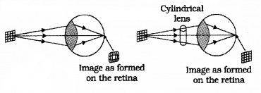
A person suffering from astigmatism cannot focus objects in front of the eye clearly. It can be corrected by using a cylindrical lens of suitable focal length.
d. Presbyopia:
It is the farsightedness occurring due to theawakening of the ciliary muscles. It can be corrected by using a lens of bifocal length.
1. The microscope:
Simple microscope: A simple microscope is a converging lens of small focal length.
Working: The object to be magnified is placed very close to the lens and the eye is positioned close to the lens on the other side. Depending upon the position of object, the position of image is changed.
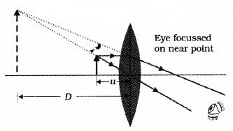
Case 1:
If the object is placed, one focal length away or less, we get an erect, magnified and virtual image at a distance so that it can be viewed comfortably ie. at 25cm or more. (This 25cm is denoted by the symbol D).
Case 2:
If the object is placed at a distance f (focal length of lens), we get the image at infinity.
The mathematical expression of magnification:
Image at D:
If the image is formed at ‘D’, we can take u = -D. Hence the lens formula can be written as
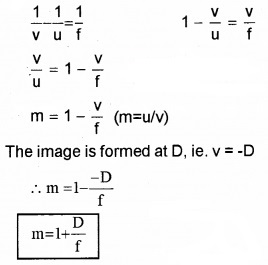
The image is formed at D, ie. v = -D
This equation is used to find magnification of simple microscope when image at D (D ≈ 25cm).
Image at infinity:
If the object is placed at f, the image forms at infinity. In this case, magnification,
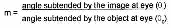
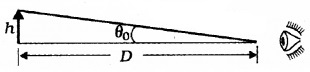
Suppose the object has a height h, the angle subtended is
tanθ0\(=\frac{h}{D}\), θ0\(=\frac{h}{D}\)______(2)
where ‘D’ is the comfortable distance of object from the eye (least distinct vision).
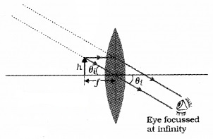
When the final image is formed at infinity,
θi = \(\frac{h^{1}}{v}\) ______(3)
When h1 is the height of image and v is the image distance
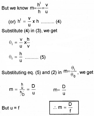
This equation is used to find magnification of simple microscope when image at infinity.
2. Compound microscope:
Apparatus: A compound microscope consists of two convex lenses, one is called the objective and the other is called eye piece.
The convex lens near to the object is called objective. The lens near to the eye is called eye piece. The two lenses are fixed at the ends of two co-axial tubes. The distance between the tubes can be adjusted.
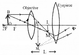
Working:
The object is placed in between F and 2F of objective lens. The objective lens forms real inverted and magnified image (I1M1) on the other side of the lens.
This image will act as object or eyepiece. Thus an enlarged, virtual, and inverted image is formed, (this image can be adjusted to be at the least distance of distinct vision, D).
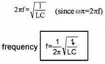
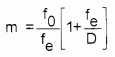
Magnification: The magnification produced by the compound microscope
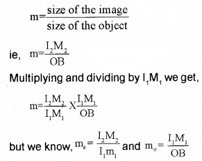
Where m0 & me are the magnifying power of objective lens and eyepiece lens.
![]()
Eyepiece acts as a simple microscope.
Therefore me = 1 + \(\frac{D}{f_{e}}\) _____(2)
m0 = \(\frac{v_{0}}{u_{0}}\) ______(3)
We know magnification of objective lens
Where v0 and u0 are the distance of the image and object from the objective lens.
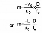
Substituting (2) and (3) in (1), we get
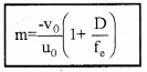
for compound microscope, uo » fo (because the object of is placed very close to the principal focus of the objective) and vo ≈ L, length of microscope (because the first image is formed very close to the eye piece).

where L is the length of microscope, f0 is the focal length of objective lens.
Case 1: If the final image is formed at infinity, magnification of eye piece D
m \(=\frac{D}{f_{e}}\)
∴ Total magnification of compound microscope
(3) Telescope: Astronomical telescope is used to observe heavenly bodies.
There are two types of telescopes
- Refracting and
- Reflecting Telescope.
(1) Refracting Telescope:
Constructional details
It consists of two convex lenses, one is called objective and other is called eyepiece. These two lenses are fitted at the ends of two coaxial tubes. The distance between the two lenses can be varied.
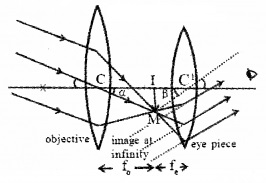
Working:
The objective lens forms the image (IM) of a distant object at its focus. This image (formed by objective) is adjusted to be focus of the eyepiece.
Magnification:
The magnifying power of a telescope is the ratio of the angle subtended by the image at the eye to the angle subtended by the object at the objective.
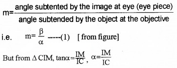
(For small values tan α ≈ α)
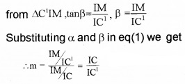
But IC = fo (the focal length objective lens) and IC1 = fe(the focal length eyepiece lens.)
∴ m = \(\frac{f_{0}}{f_{e}}\)
In this case the length of the telescope tube is (f0 + fe).
Case 1: When the image formed by the objective is within the focal length of the eyepiece, Then the final image is formed at the least distant of distinct vision. In this case, magnifying power.
(2) Reflecting Telescope:
Newtonian types reflecting Telescope:
The Newtonian reflector consists of a parabolic mirror made of an alloy of copper and tin. It is fixed atone end of a metal tube.
The parallel rays from a distant stars incident on the mirror M1. After reflection from the mirror, the ray incident on a plane mirror M2.
The reflected ray from M2 enter into eye piece E. The eyepiece forms a magnified, virtual and erect image. Magnifying power of Newton Telescope
m = \(\frac{f_{0}}{f_{e}}\) or m = \(\frac{R}{2 f_{\theta_{g}}}\)
where
fo — is the focal length of concave mirror
f2 — is the focal length of eyepiece.
R – Radius of curvature of concave reflector.
We hope the Plus Two Physics Notes Chapter 9 Ray Optics and Optical Instruments help you. If you have any query regarding Plus Two Physics Notes Chapter 9 Ray Optics and Optical Instruments, drop a comment below and we will get back to you at the earliest.