CBSE Class 10 Science Lab Manual – Resistors in Series
Aim
To determine the equivalent resistance of two resistors, when connected in series combination.
Materials Required
Two standard resistance coils (or resistors), ammeter (0-1.5A), voltmeter (0-1.5V), one-way key, low resistance rheostat, connecting wires, a piece of sand paper and ceil or battery eliminator.
Theory/Principle
The end-to-end connection of two or more resistors is said to be series combination, if they. provide only one path to the flow of current, i.e. same current would be flown through each resistor.
Consider V be the potential difference by one DC source across the combination of unknown resistances R1 and R2 [as shown in Fig. 1(b)].
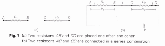
If V1 and V2 be the potential differences measured by the voltmeter across each resistor, then
V =V1 +V2 ………(i)
According to Ohm’s law,
V1 = IR1, V2 = IR2
and V = IRs ……..(ii)
where, Rs = Equivalent resistance of R1 and R2 in series combination.
From Eqs. (i) and (ii), we get
IRs = IR1 + IR2
=> Rs =R1 + R2
Thus, the equivalent resistance of the series combination is equal to the sum of the individual resistances connected in the series circuit.
Procedure
- Note the least count and the zero error (if any) of the given ammeter and voltmeter.
- Clean the ends of connecting wires using a sand paper.
- Find the values of two given resistances R1 and R2 by the procedure given in Experiment 5.
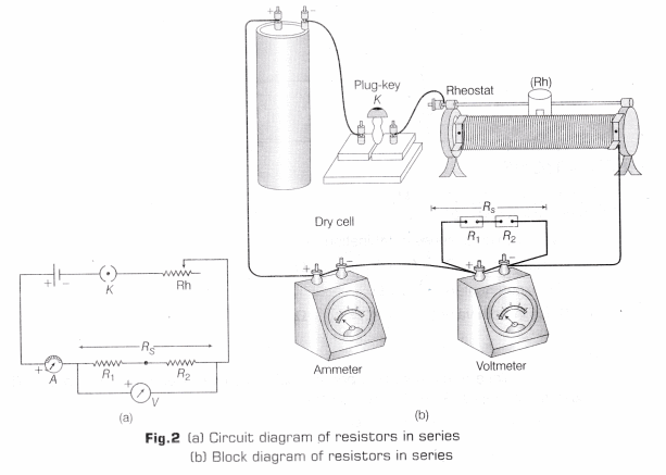
- Connect the resistances in series as shown in block diagram or circuit diagram given in Fig. 2.
- Put the plug in the key and take the readings of ammeter and voltmeter (as done in Experiment 5).
- Repeat the step 5 three times by changing the position of the sliding contact of the rheostat (as done in Experiment 5).
- Tabulate the readings and find the ratio of V and I. It will give the equivalent resistance of the combination.
Observation
- Least count of ammeter = …………. A
- Zero error of ammeter = ………… A
- Least count of voltmeter = ………… V
- Zero error of voltmeter = …………. V
- Zero correction in ammeter reading = ………. A
- Zero correction in voltmeter reading = ……… V
Resistor used Observations Voltmeter reading (volt) Ammeter
Reading (ampere)R=V/I
(ohm)Mean value of
resistance (ohm)R1 (a)
(b)
(c)R1 (a)
(b)
(c)Rs = R1+R2 (a)
(b)
(c)
Calculations
- Mean value of R1 = ………. Ω
- Mean value of R2 = ……….. Ω
- Equivalent value of series combination,
- By calculation, R’s = R1 + R2 = ………… Ω
- By experiment, Rs = ………… Ω
Difference in both values, Rs -R’s = ……… Ω
Result
- There is a close agreement between the calculated value and the value obtained by the experiment.
Hence, Rs = R1 + R2 is verified. - Equivalent resistance, Rs = …………. Ω
Percentage Error
It can be found by using the following relation:
Percentage Error = \(\frac { Experimental\quad value-Calculated\quad Value }{ Calculated\quad Value } \times 100\)
= \(\frac { { R }_{ s }-{ R’ }_{ s } }{ { R’ }_{ s } } \times 100\) = …….. %
It shows that the percentage error is within the experimental error.
Precautions
- Remove the dust and other insulating particles from the ends of connecting wire, by rubbing it with sand paper.
- All the connections should be tight and properly done as per the circuit diagram.
- Take out the plug from the plug key in between the two observations.
- A low resistance rheostat should be used in the circuit to obtain a large variation in the current.
- The thick copper connecting wires should be used in the circuit.
- The positive terminal of the ammeter and voltmeter must be connected to the positive terminal of the battery or battery eliminator.
- Never connect the two terminals of the cell without any resistance.
- The pointers of the ammeter and voltmeter should be at zero mark when no current flows through them.
- Current should be passed through the circuit for a short time while taking observations; otherwise current would cause unnecessary heating in the circuit. Heating may change the resistance of resistors.
- The ammeter should be connected in series with the combination of resistors such that the current enters at the positive terminal and leaves at the negative terminal of the ammeter.
- Voltmeter should always be connected in parallel to the combination of resistors.
Sources of Error
- Reading error may be possible while observing the pointer of ammeter and voltmeter.
- Thick connecting wires may not be available at the time of performing the experiment.
- Area of cross-section of resistance may not be uniform across the length of the wire.
- The high resistance rheostat may be used.
- Current may be allowed for the longer period through the circuit.
- The terminal screws of the given instruments may not be tighten properly.
Viva – Voce
Question 1.
If two resistors having resistances of 2 Ω and 4 Ω, respectively are connected in a series combination in an electric circuit, what will be the net resistance in the Circuit? [NCERT]
Answer:
According to series combination, Rnet =R1+R2
⇒ Rnet = (2 + 4) Ω {∵R1 = 2 Ω, R2 = 4Ω}
⇒ Rnet = 6 Ω
Question 2.
In an electric circuit, a resistor of 5 Ω resistance is connected to a battery (5V), through an ammeter and a plug key. Now in this circuit, an another resistor of 10 Ω is connected in series with the 5 Ω resistor. Will there be any change in the ammeter reading? How much? [NCERT]
Answer:
Since, resistors are added in series, therefore there will be a change in the current.
I1 = \(\frac { V }{ R } =\frac { 5 }{ 5 }\) =1A
and I2 = \(\frac { V }{ { R }_{ 1 }+{ R }_{ 2 } } =\frac { 5 }{ 10+5 } =\frac { 1 }{ 3 } A\)
Therefore, change in ammeter reading will be from 1 A to 0.33 A.
Question 3.
In the above question, what is the potential difference across two ends of the resistor of 5 Ω resistance, when it is alone in the circuit? What is the potential difference across the two ends of resistor of 5 Ω resistance, when it is connected in series with the resistor of 10 Ω resistance? What is the potential difference across the series combination? [NCERT]
Answer:
Consider V1 be the potential difference across two ends of the resistor of 5 Ω resistance, when it is connected alone.
=> V1 = I1R = \(\frac { 1 }{ 3 }\) x 5 = \(\frac { 5 }{ 3 }\) V
Consider V2 be the potential difference across two ends of resistor of 5 Ω resistance, when it is connected to 10 Ω resistor in series.
=> V2 = I2R = \(\frac { 1 }{ 3 }\) x 5 = \(\frac { 5 }{ 3 }\) V
Potential difference across the series combination is V3 = I2Rs = \(\frac { 1 }{ 3 }\) x (5 +10) = \(\frac { 1 }{ 3 }\) x 15 = 5V
The potential difference across series combination is equal to applied potential difference.
Question 4.
How will you find the equivalent resistance, when they are connected in series?
Answer:
The equivalent resistance of two resistors R1 and R2, is determined by
Rs = R1 + R2
Question 5.
What is the relationship between V and R for the series combination?
Answer:
Voltage applied across combination of resistances is directly proportional to the resistance of series combination.
Question 6.
What happens to the resistance of the resistor, if the current through it increases?
Answer:
It remains unchanged because the resistance does not depend on the current flowing through it.
Question 7.
When two unequal resistances are connected in series, what will be the potential difference across each resistor?
Answer:
When two unequal resistances are connected in series, the potential difference across each resistor will be different.
Question 8.
What happens to the ammeter reading if two resistors of the same value are connected in series in the circuit?
Answer:
The deflection in ammeter is reduced to half of the previous value, i.e. ammeter shows half of the previous reading.
Question 9.
Why resistance becomes more in series combination?
Answer:
The effective length of all the resistors in series combination increases. Hence, equivalent resistance of the combination increases as R ∝ I
Question 10.
When do we put the resistances in series combination?
Answer:
A, When we have the smaller value of resistance and need the greater value of resistance, we put them in series combination.
Question 11.
In a circuit, if two resistors of resistances 5Ω and 10Ω are connected in series. Compare the current passing through the two resistors.
Answer:
In a series combination, same current passes through all the resistors. Thus, the ratio of current will be 1:1.
Question 12.
Why current should be passed for a short time through the circuit while taking observations?
Answer:
Current passed through the circuit for longer time while taking observations, can cause unnecessary heating in the circuit, which may change the resistance of resistors.
Question 13.
Mention the use of rheostat in the circuit.
Answer:
To change the current in the circuit which can be done by changing the sliding contact of the rheostat.
Question 14.
Can you mention one disadvantage of series connection?
Answer:
In series connection, if any one component fails to work, the circuit breaks and none of the components works.
Science Lab ManualScience Practical SkillsScience LabsMath LabsMath Labs with Activity