What is Refraction of Light
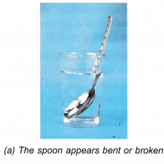
When a spoon is immersed into a glass of water, the spoon appears bent or broken as shown in Figure (a).
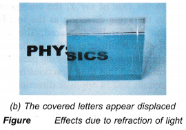
When a part of the word PHYSICS is covered with a glass slab as shown in Figure (b), the covered letters appear displaced.
The two situations described are perceptions due to the change of the direction of a light ray when it leaves the water or the glass and enters the air.
Definition: When light rays travelling in a medium are incident on a transparent surface of another medium they are bent as they travel in second medium.
People also ask
- Examples of refraction of light
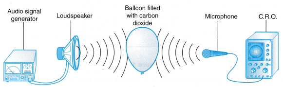
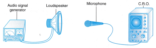
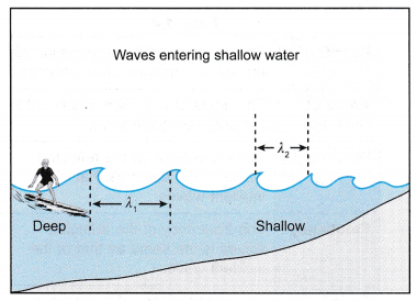
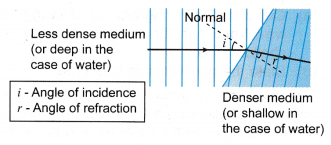
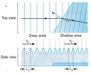
- Analysing Refraction of Waves
- What is the index of refraction?
- What is atmospheric refraction?
- Refraction of light through glass slab
Some Associated Terms
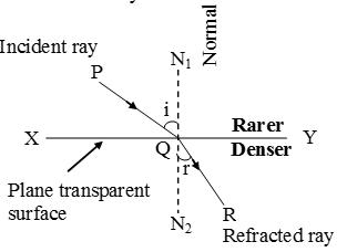
- Transparent surface: The plane surface which refracts light, is called transparent surface. In diagram, XY is the section of a plane transparent surface.
- Point of incidence: The point on transparent surface, where the ray of light meets it, is called point of incidence. In diagram, Q is the point of incidence.
- Normal: Perpendicular drawn on the transparent surface at the point of incidence, is called normal. In diagram, N1QN2 is the normal on surface XY.
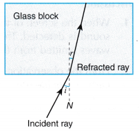
- Incident ray: The ray of light which strikes the transparent surface at the point of incidence, is called incident ray in diagram PQ is the incident ray.
- Refracted ray: The ray of light which travels from the point of incidence into the other medium, is called refracted ray. In diagram, QR is the refracted ray.
- Angle of incidence: The angle between the incident ray and the normal on the transparent surface at the point of incidence, is called the angle of incidence. It is represented by the symbol i. In diagram, angle PQN1 is the angle of incidence.
- Angle of refraction: The angle between the refracted ray and the normal on the transparent surface at the point of incidence, is called angle of refraction. It is represented by symbol r. In diagram angle RQN2 is the angle of refraction.
- Plane of incidence: The plane containing the normal and the incident ray, is called plane of incidence. For the diagram, plane of book page is the plane of incidence.
- Plane of refraction: The plane containing the normal and the refracted ray, is called plane of refraction. For the diagram, plane of book page is the plane of refraction.
Refraction of Light
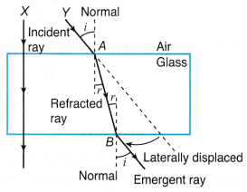
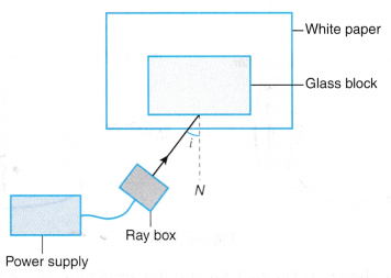
- Figure shows how light rays pass through a glass block. From the figure:
- When a light ray (X) is incident normal (∠i = 0) to the boundary of the media (air to glass), it travels straight on without being bent.
- When a light ray (Y) is incident at an acute angle to the boundary of the media, the light ray is bent or refracted.
- The light ray bends towards the normal when it travels from a less dense medium (air) to a denser medium (glass).
- The light ray bends away from the normal when it travels from a denser medium (glass) to a less dense medium (air).
- The angle of refraction (∠r) is always smaller than the angle of incidence (∠i) when light travels from a less dense medium to a denser medium.
- In the case of ray Y, the emergent ray is in the same direction as the incident ray but is laterally displaced. This is due to the two boundaries of the media, where the refractions occurred, being parallel to each other and that the refractions bend the ray equally and in opposite directions.
- There is another interesting phenomenon which you can observe from Figure. At point A, ray Y travels from air to glass with an angle of incidence, i and an angle of refraction, r. At point B, ray Y travels from glass to air with an angle of incidence, r and an angle of refraction, i. It can be said that the ray, at point B, is travelling the exact same path as compared to point A, but in the opposite direction. This is the principle of reversibility of light.
- Refraction of light is the bending of a light ray at the boundary as it travels from one medium to another.
- Any substance that a light ray travels through is called a medium.
- A medium, which is optically less dense or denser, has no connection with the formula,
Density = Mass/Volume It is related only to the speed of light that travels through it. (All references to less dense and denser medium in this chapter is taken to mean optically less dense or denser.) - The more optically dense a medium is, the slower light travels through it.
- A light ray travels much slower in a denser medium. When a light ray travels from one medium to another, its speed changes. The change in speed of the light ray causes it to change its direction.
- The effect of refraction can also be explained by using the analogy of a car moving onto a sandy road as shown in Figure.
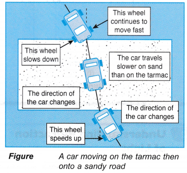
- As one of the front wheels of the car hits the sand, it slows down while the other wheel keeps going at its original speed. This will cause the direction of the car to change. The new direction of the car will be closer to the normal.
Laws of Refraction of Light
First Law: The incident ray, the normal to the transparent surface at the point of incidence and the refracted ray, all lie in one and the same plane.
Second Law : The ratio of sine of angle of incidence to the sine of the angle of refraction is constant and is called refractive index of the second medium with respect to the first medium.
\(\frac{\text{sin i}}{\text{sin r}}=\text{ }\!\!\mu\!\!\text{ }\)
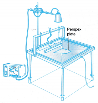
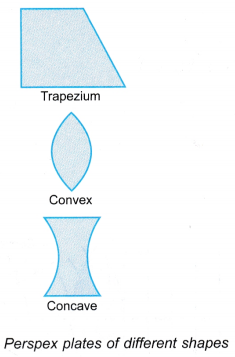
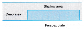
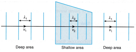
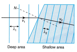
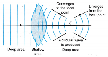
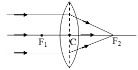
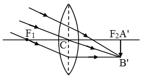
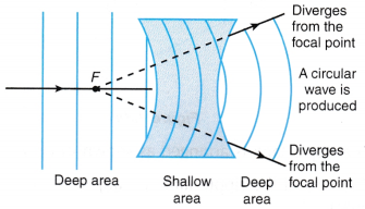 The above Figures show the observed wavefronts for the respective perspex plates.
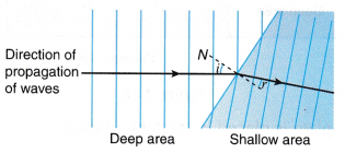
 Discussion: