Analysing Diffraction of Waves
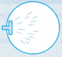
- Figure shows a scenery of a fishing village. It is noticed that when the waves passed through the narrow opening between the two concrete barriers, their shape changed. This observation can be explained by the diffraction of waves.
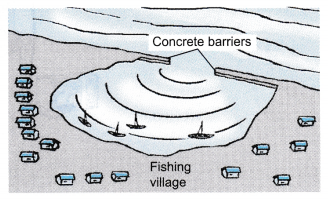
- Diffraction of waves is a phenomenon that refers to the spreading out of waves when they move through a gap or round an obstacle.
People also ask
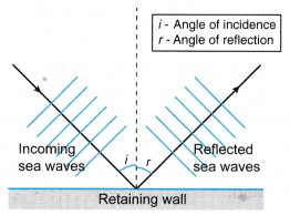
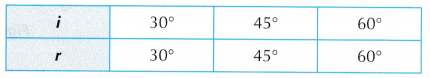
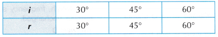
- Analysing Reflection of Waves
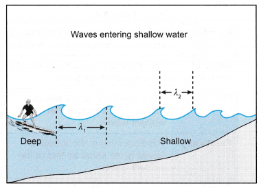
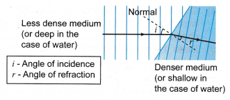
- Analysing Refraction of Waves
- Analysing Interference of Waves
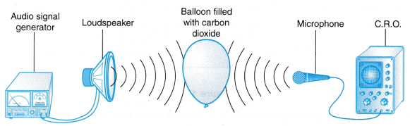
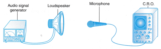
- Analysing Sound Waves
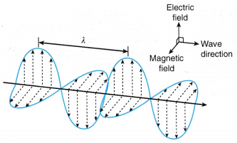
- Analysing Electromagnetic Waves
Characteristics of Diffraction of Waves
Wavelength: The wavelength of the diffracted waves is the same as that of the incident waves.
Frequency: The frequency of the diffracted waves is the same as that of the incident waves.
Speed: The speed of the diffracted waves is the same as that of the incident waves.
Direction: The direction of propagation of the diffracted waves depends on the width of the gaps or obstacles. For smaller gaps and obstacles, the change of direction is more – the spread is bigger.
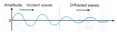
Amplitude: The amplitude of the diffracted waves is smaller than that of the incident waves.
Diffraction of Plane Waves in a Ripple Tank Experiment
Aim: To study the characteristics of diffraction of plane waves in a ripple tank.
Material: White paper as screen
Apparatus: Ripple tank with its accessories, stroboscope
Method:
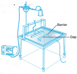
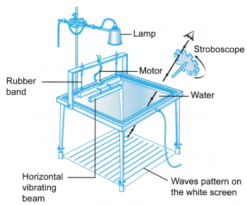
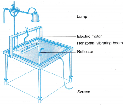
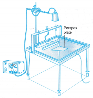
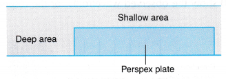
- The ripple tank is arranged as shown in Figure.
- The legs of the ripple tank are adjusted so that the base of the tank is horizontal. The tank is filled with water.
- A horizontal vibrating beam is used to create plane waves.
- The speed of the motor is adjusted to produce a train of waves that can be clearly observed on the screen with the help of a stroboscope.
- The barriers are adjusted for different widths of the gap.
- The wavefronts that emerge from the gap are observed and recorded.
- The width of the gap is fixed but the frequency of the motor is adjusted.
- The wavefronts that emerge from the gap are observed and recorded.
- The barriers are replaced with obstacles of different widths and the ‘shadow’ of each obstacle is observed and recorded.
Observations:
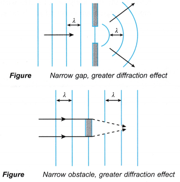
 The above figures shows the diffracted wavefronts.
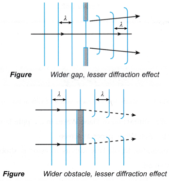
Discussion:
- It is observed that the effect of diffraction is greater when the width of the gap or obstacle is smaller.
- Waves passing through a narrow gap spread out wider than waves passing through a wide gap.
- An obstacle placed in front of incoming incident waves will cause a ‘shadow’ behind the obstacle. For a narrow obstacle, the wavefronts meet and rejoin at a place nearer to the obstacle as compared with a wider obstacle.
Diffraction of Light Experiment
Aim: To study the characteristics of diffraction of light.
Material: White paper as screen
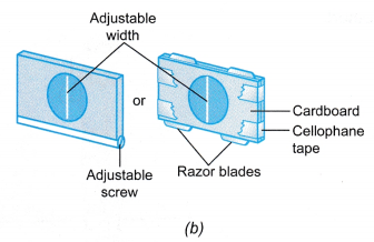
Apparatus: Laser pen, two retort stands with clamps, adjustable single-slit
Method:
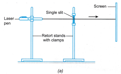
- The apparatus is set up as shown in Figure (a).
- A ray of light from the laser pen is directed through the adjustable single-slit onto the screen.
- The distance and the positions of the laser pen and the single-slit are adjusted until a clear diffraction pattern of light from the laser beam falls on the screen.
- The width of the single-slit is adjusted and the pattern on the screen is observed for different widths of the slit.
- The single-slit is replaced with a piece of black paper with a tiny pinhole in it.
- A ray of light from the laser pen is directed through the hole and the pattern formed on the screen is observed.
- The hole is enlarged and step 6 is repeated.
Observations:
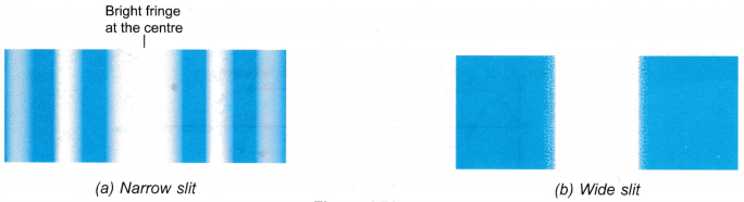
- From the observation in step 4, the patterns formed by the slits are as shown in Figure.
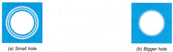
- From the observation in steps 6 and 7, the patterns formed by the holes are as shown in Figure.
Discussion:
- Light undergoes diffraction when passing through a narrow slit and a small hole.
- The diffraction pattern becomes less distinct when the slit or hole becomes wider.
Diffraction of Sound Waves Experiment
Aim: To study the characteristics of diffraction of sound waves
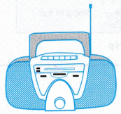
Apparatus: A cassette or CD player
Method:
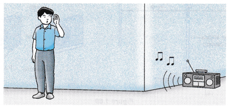
- Carry out the outdoor activity as shown in Figure.
- Listen to the music from the cassette or CD player at a position that is blocked by a corner of a building as shown in the diagram.
Observation:
- The music from the cassette or CD player can be heard although it is blocked by the corner of the building. Discussion:
- The music from the cassette or CD player can be heard even though it was blocked by the building. This shows that diffraction of sound waves has occurred.
Conclusions:
- Diffraction of waves occurs when there is a spreading out of waves when the waves move through a gap or round an obstacle.
- The wavelength, frequency and speed of the diffracted waves are the same as that of the incident waves.
- However, due to the spreading of the waves, the energy per unit area of the diffracted waves is less than the incident waves. Hence, the amplitude of the diffracted waves is smaller than the incident waves.
 (a) When a steady train of waves move across the water surface, each wave crest acts like a convex lens and concentrates the light on the screen as shown in Figure. Flence, a bright pattern on the screen corresponds to a crest of the waves.
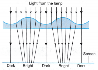 (b) A stroboscope is normally used to observe wave patterns on the screen. By rotating the stroboscope at the same frequency as the motor of the ripple tank kit, the motion of the waves can be frozen for more detailed observation.
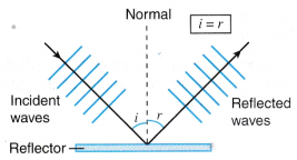
 Discussion:
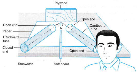
 Discussion:
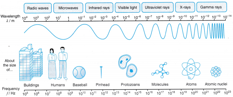


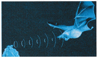 (a) When these waves hit an object, they are reflected back and received by the bat.
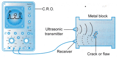 (a) An ultrasonic transmitter sends out pulses of ultrasound in the metal.
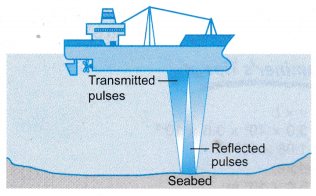 (a) Pulses of ultrasounds are directed from the ship to the seabed and a receiver attached to the ship detects the reflected pulses.
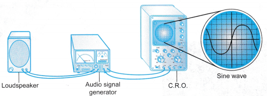
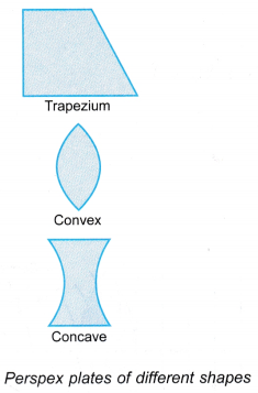
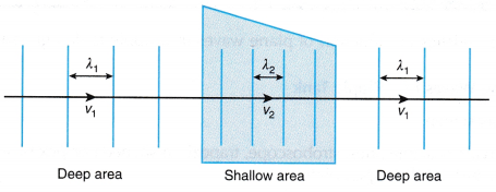
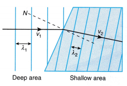
 The above Figures show the observed wavefronts for the respective perspex plates.
 Discussion: