Describe the turning effect on a current carrying coil in a magnetic field
- A current-carrying coil in a magnetic field experiences a turning effect.
- In Figure, a rectangular coil ABCD carries a current in the magnetic field between two magnadur magnets.
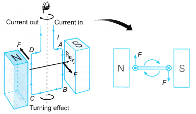 (a) The sides BC and DA carry currents with directions parallel to the magnetic field. No force is exerted on these two sides.
(b) The side AB next to the South pole experiences a force. The direction of the force can be determined using Flemings left -hand rule or the right-hand slap rule.
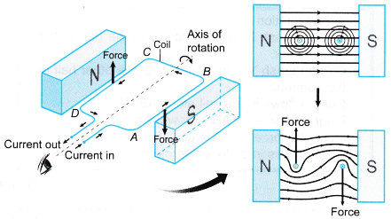
(c) The side CD experiences a force that acts in the opposite direction. - The two forces acting in opposite directions on the two sides of the coil form a couple and produces a turning effect on the coil.
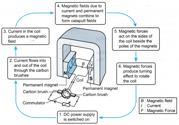
- The forces are produced when the magnetic field due to the current in the coil combines with the external magnetic field to produce two resultant catapult fields around the coil as shown in Figure.
- Two important applications of the turning effect of a current-carrying coil in a magnetic field are the direct current motor and the moving-coil galvanometer.
People also ask
- What is the electromagnetic induction?
- What is Faraday’s law?
- What are the laws of electromagnetic induction?
- What is Lenz’s law of electromagnetic induction?
- What is alternating current and direct current?
- What is the Working Principle of AC Generator?
- What is the Working Principle of DC Generator?
- What is the Principle of DC Motor?
- What is magnetic force on a current carrying conductor?
- What is the Meaning of Magnetic Force?
- What factors affect the strength of an electromagnet?
- What is the Magnetic Field?
- What Is Magnetic Effect Of Electric Current?
- Oersted Experiment on Magnetic Effect of Current
- How do you Determine the Direction of the Magnetic Field?
Relate this turning effect to the action of an electric motor
The Direct Current Motor
- The direct current motor (d.c. motor) uses the turning effect on a current-carrying coil in a magnetic field.
- The operation of the direct current motor is explained in Figure.
First half-rotation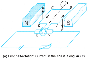
- Carbon brush X is in contact with the half of the commutator.
- Carbon brush Y is in contact with the other half of the commutator.
- Current flows in the coil along ABCD.
- Magnetic force on AB is downwards.
- Magnetic force in CD is upwards.
- Coils rotates in a clockwise direction.
Second half-rotation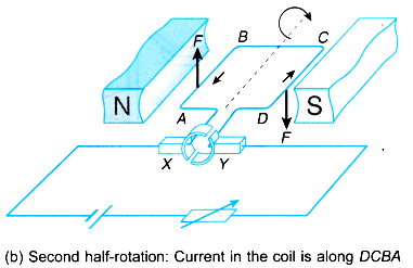
- Carbon brush X is in contact with the half of the commutator.
- Carbon brush Y is in contact with the other half of the commutator.
- Current flows in the coil along DCBA.
- Magnetic force on CD is downwards.
- Magnetic force in AB is upwards.
- Coils continues to rotate in a clockwise direction.
Turning effect to the action of an electric motor Experiment
Aim: To investigate the factors that affect the speed of rotation of an electric motor.
Materials: Insulated copper wire (s.w.g. 26), wooden former, a thin iron rod to act as an axle, wooden block as the base, a pair of magnadur magnets with U-shaped steel yoke, two split-pins, cellophane tape
Apparatus: Low voltage d.c. power supply
Method: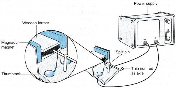
- The apparatus is set up as shown in Figure. The coil with 40 turns round the wooden former is used.
- The voltage of the d.c. power supply is set to 1 V. The power supply is switched on and the speed of rotation of the motor is observed.
- Step 2 is repeated with a voltage of 2 V.
- The voltage of the d.c. power supply is set back to 1 V.
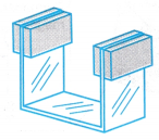
- Another pair of magnadur magnets is added to the U-shaped steel yoke as shown in Figure. The power supply is switched on and the speed of rotation of the motor is observed.
- One pair of the magnadur magnets is removed. The coil is replaced with another coil of 80 turns of wire. The power supply is switched on and the speed of rotation of the motor is observed.
Observations:
| Steps taken | D.C. power supply | Magnadur magnets | Number of turns in coil | Rotation of coil |
| Step 2 | 1 V | 1 pair | 40 turns | Medium speed |
| Step 3 | 2 V | 1 pair | 40 turns | Higher speed |
| Step 5 | 1 V | 2 pairs | 40 turns | Higher speed |
| Step 6 | 1 V | 1 pair | 80 turns | Higher speed |
Discussion:
- The current is proportional to the voltage supplied. By comparing the observations in steps 2 and 3, the speed of rotation increases when the voltage supplied is increased. Therefore, the speed of rotation increases when the current in the coil is increased.
- The strength of the magnetic field is increased by adding one more pair of magnadur magnets. By comparing the observations in steps 2 and 5, the speed of rotation increases when the strength of the magnetic field is increased.
- By comparing the observations in steps 2 and. 6, the speed of rotation increases when the number of turns of the coil is increased.
Conclusion:
The speed of rotation of an electric motor increases when the current in the coil, the strength of the magnetic field or the number of turns of the coil is increased.
Turning Effect in Moving-coil Ammeter or Voltmeter
Moving-coil Ammeter or Voltmeter
- Figure (a) shows a moving coil voltmeter commonly used in the school laboratory. Figure (b) shows the internal parts of the voltmeter.
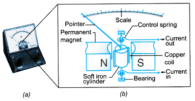
- When a current passes through the coil, equal and opposite parallel forces act respectively on the sides of the coil beside the poles of the permanent magnet.
- This pair of forces produces a turning effect to rotate the coil until it is stopped by the control springs.
- The pointer fixed to the coil deflects to show a reading on the scale.
- When the power supply is switched off, the forces no longer exist. The control springs bring the coil back to its original position and the pointer goes back to zero.
- The ends of the permanent magnet are concave to produce a radial magnetic field so that the scale of the meter is linear.