To Construct Optical Devices Using Lenses

To Construct Optical Devices Using Lenses

To Construct a Compound Microscope

  1. The materials required for the construction of a compound microscope:
    (a) A convex lens with a power of +20 D (f0 = 5.0 cm) and a large diameter is used as the objective lens.
    (b) A convex lens with a power of +14.3 D (fe = 7.0 cm) and a small diameter is used as the eyepiece.
    (c) A cardboard tube with a diameter similar to the objective lens and a cardboard tube with a diameter similar to the eyepiece.
    The Uses of Lenses in Optical Devices
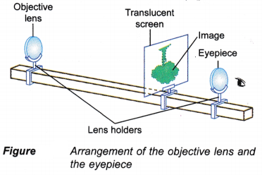
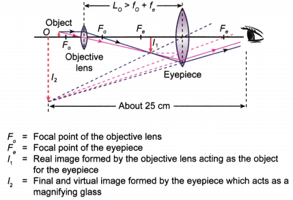
  2. A small sheet of graph paper (as object) is placed in front of the objective lens. The distance of the graph paper is adjusted to slightly greater than 5 cm (2f > u > f). A lamp is directed at the graph paper.
  3. The translucent screen is adjusted until a real, inverted and magnified image is formed.
  4. The distance of the eyepiece is slowly adjusted until a clear and very large image (a few times larger) is seen through the eyepiece.
  5. The translucent screen is then removed. The set-up of the lenses can function as a compound microscope.
  6. The distance between the objective lens and the eyepiece is measured. This distance is greater than the sum of the focal lengths of the objective lens and the eyepiece:
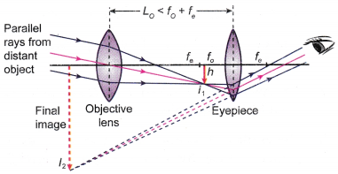
    L> f0+ fe (5 cm + 7 cm)
  7. The objective lens and the eyepiece are then fitted into the tubes as shown in Figure.
    To Construct Optical Devices Using Lenses 1
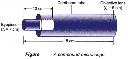
  8. This is a simple compound microscope constructed by using two high power convex lenses.

People also ask

To Construct an Astronomical Telescope

  1. The materials required for the construction of an astronomical telescope:
    (a) A convex lens with a power of +2 D (f0 = 50.0 cm) and a large diameter is used as the objective lens.
    (b) A convex lens with a power of +10 D (fe = 10.0 cm) and small diameter is used as the eyepiece.
    (c) A cardboard tube with a diameter similar to the objective lens and a cardboard tube with a diameter similar to the eyepiece.
  2. The objective lens and the eyepiece are arranged as shown in Figure.
    To Construct Optical Devices Using Lenses 2
  3. The objective lens is then directed to a distant object. A translucent screen is placed about 50 cm from the objective lens and is adjusted until a sharp image is seen on the screen.
  4. The eyepiece that is placed in front of the translucent screen is adjusted until a clear and magnified image is seen through the eyepiece.
  5. The translucent screen is removed and the set¬up of the lenses can function as an astronomical telescope.
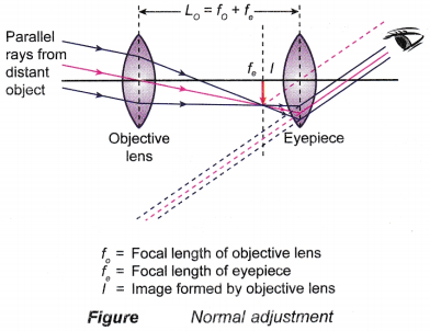
  6. The distance between the two lenses is measured. This distance is less than or equal to the sum of the focal lengths of the two lenses:
    L0 ≤ f0+ fe (50 cm + 10 cm)
  7. The objective lens and the eyepiece are then fitted into the tubes as shown in Figure.
    To Construct Optical Devices Using Lenses 3
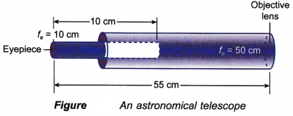
  8. This is a simple astronomical telescope constructed by using a low power lens and a high power lens.

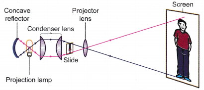
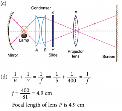
Example: Figure shows the arrangement of an optical system in a slide projector. The slide, XY is put upside down.
To Construct Optical Devices Using Lenses 4
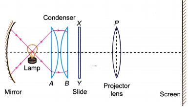
(a) Why does the slide have to be put upside down into the slide projector?
(b) The lamp is placed at the focal point of lens A and at the centre of curvature of the concave mirror. Why?
(c) Complete the ray diagram from lens B onwards, to show how the projector lens forms an image of the slide on the screen.
(d) If the slide is placed 5 cm from lens P, the screen has to be placed 4 m from the lens to form a sharp image. What is the focal length of lens P?
(e) The screen is now moved to a new position. It is found that lens P has to be adjusted further away from the slide in order to give a sharp image on the screen.
(i) Has the screen been moved nearer to or further away from the projector?
(ii) What change, in brightness and size, has occurred to the image?
(f) What would happen if the distance between lens P and the slide is reduced to its focal length?
Solution:
(a) Real images that can be projected on the screen are always inverted. Therefore, the slide has to be upside down so that the image will be seen upright.
(b) The lamp is placed at the centre of curvature of the concave mirror so that all light rays behind the lamp are reflected back along the same path to the condenser. The lamp is placed at the focal point of lens A so that all light rays passing through it become parallel and spread evenly on the whole slide after passing through lens B.
To Construct Optical Devices Using Lenses 5
(e) (i) The screen has been moved nearer to the projector.
(ii) The image is brighter and smaller.
(f) No image is formed on the screen.

The Uses of Lenses in Optical Devices

The Uses of Lenses in Optical Devices

Simple Microscope

The Uses of Lenses in Optical Devices

  1. A magnifying glass is the simplest microscope. It consists of a single convex lens with short focal length.
  2. When the magnifying glass is held near to the eye and the object is placed inside its focal length (u < f), a virtual, magnified and upright image is produced.
  3. A sharper and larger image is seen at the near point.
  4. In general, the near point is taken as 25 cm. This is the closest distance at which an object/image can be brought into focus by the eye.

People also ask


Compound Microscope

The Uses of Lenses in Optical Devices 1

  1. A compound microscope is an optical instrument used to view near and very small objects. It is made up of two powerful convex lenses, the objective lens and the eyepiece, of short focal lengths ranging from 5.0 cm to 10.0 cm.
  2. The objective lens is the lens nearer to the object. The more powerful lens or the lens with a shorter focal length is used as the objective lens.
  3. The objective lens is used to produce a real, inverted and magnified image, I1.
  4. The object to be observed must be placed between F0 and 2F0 of the objective lens.
  5. The eyepiece functions as a magnifying glass. It is used to magnify the first image, formed by the objective lens.
  6. The eyepiece must be positioned so that the first image, I1 is between the lens and the focal point of the eyepiece, Fe.
  7. In normal adjustment, the combination of the two lenses of the microscope produces a final image, I2 which is inverted with respect to the object, O.
  8. The final image, I2 formed by the eyepiece, is virtual, inverted with respect to the object, O and magnified.
  9. The final image, I2 will be at the near point, about 25 cm from the eye.
  10. In normal adjustment, the distance between the lenses is greater than the sum of their focal lengths, L0 > f0 + fe.
  11. If the height of the object is h0, the height of the image, I1 is h1 and the height of the final image, I2 is h2, then the magnification produced by the objective lens is:
    The Uses of Lenses in Optical Devices 2
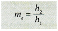
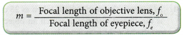
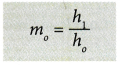
and the magnification produced by the eyepiece is:
    The Uses of Lenses in Optical Devices 3
  12. The magnification of a compound microscope is:
    The Uses of Lenses in Optical Devices 4

Astronomical Telescope

The Uses of Lenses in Optical Devices 5

  1. An astronomical telescope is an optical instrument used to view distant objects. It is made up of two convex lenses, the objective lens and the eyepiece.
  2. The objective lens has a low power (long focal length) whereas the eyepiece has a high power (short focal length).
  3. The objective lens converges the parallel rays from a distant object and forms a real, inverted and diminished image, I1 at its focal point, F0.
  4. The eyepiece functions as a magnifying glass. It is used to produce a virtual, upright and magnified image, I2.
  5. When the telescope is used in normal adjustment, the final image is produced at infinity as shown in Figure.
    The Uses of Lenses in Optical Devices 6
  6. This is done by adjusting the position of the eyepiece so that the image formed by the objective lens, I becomes the object at the focal point, Fe of the eyepiece.
  7. In normal adjustment, the distance between the lenses is equal to the sum of their individual focal lengths, L = f+ fe.
  8. The magnification of the telescope in normal adjustment is given by:
    The Uses of Lenses in Optical Devices 7

Differences and similarities between a compound microscope and an astronomical telescope

Compound microscopeAstronomical telescope
Consists of two high powered convex lenses (+20 D and +14 D).Consists of a high powered (+14 D) and a low powered (+2 D) convex lenses.
The focal length of the objective lens is shorter than the focal length of the eyepiece (f0 < fe).The focal length of the objective lens is longer than the focal length of the eyepiece (f0 > fe).
Image formed by the objective lens is magnified.Image formed by the objective lens is diminished.
In normal adjustment, the final image is at the near point.In normal adjustment, the final image is at infinity.
Distance between the objective lens and the eyepiece:
L0 > f0 + fe
Distance between the objective lens and the eyepiece:
L0 ≤ f0 + fe
Similarities:

  • Consists of two convex lenses.
  • Objective lens forms a real and inverted image which acts as the object for the eyepiece.
  • The eyepiece acts as a magnifying glass.
  • Final image formed is virtual, inverted with respect to the object and magnified.

Single-lens Camera

The Uses of Lenses in Optical Devices 8

  1. A typical camera consists of a light-proof box with a convex lens mounted at the front and a roll of film placed at the back.
  2. The basic structure of a camera is shown in Figure. It consists of a convex lens, a film, a shutter and a diaphragm.
  3. The convex lens is used to produce a real and inverted (and usually diminished) image on a light-sensitive film placed at the back of the camera.
  4. The focusing screw is used to focus the image on the film.
  5. For a distant object, the image is formed near the focal point, F. The focusing screw is adjusted to move the focal point, F towards the film so as to get a sharp image on the film.
  6. For a near object, the image is formed at a distance greater than the focal length of the lens. The focusing screw is adjusted to move the focal point, F away from the film in order to obtain a sharp image on the film.
  7. The diaphragm is used to adjust the size of the aperture, which controls the amount of light entering the camera. The actual function of the aperture is to control the depth of field.
  8. The shutter controls whether light is allowed to reach the film or not. The speed of the opening and closing of the shutter is used to control the exposure time when taking a photograph.

Slide Projector

The Uses of Lenses in Optical Devices 9

  1. A slide projector is a device used to view photographic slides. It has four main parts, a projection lamp, a concave reflector, a condensing lens and a projector lens.
  2. When light from the projection lamp passes through the slide and projector lens, the resulting image is enlarged and projected onto a perpendicular flat screen where the audience can view the reflection of the slide.
  3. The slide being the object, is placed between f and 2f from the projector lens, where f is the focal length of the projector lens. The image formed on the screen is real, inverted and magnified.
  4. For an image of higher magnification to be formed on the screen, the slide is placed closer to f and the screen is placed further.
  5. The projection lamp is placed at the centre of curvature, C of the concave reflector so that all the light towards the reflector can be reflected back to the same path of the condenser lens. The condenser lens consists of two plano-convex lenses separated by a heat filter. The heat filter is to protect the slide from being overheated by the lamp.
  6. The projection lamp is also placed at the focal point of the condenser lens. The direct light from the lamp and the reflected light from the concave reflector spread out evenly over the surface of the slide after passing through the condenser lens.
  7. The movable projector lens focuses a sharp, inverted and magnified image onto a screen.
  8. The slide has to be placed upside down in order to form an upright image on the screen.