How Does a Transformer Work?
Figure shows a power supply unit found in school laboratories. It is connected to the mains supply which supplies it with an input voltage of 240 V. Using the voltage selector, you can select output voltages from 2 V to 12 V. What changes the input voltage from 240 V to a lower output voltage?
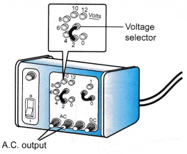 The main component found inside the power supply unit is a transformer. Transformers can decrease or increase the a.c. voltage supplied to it.
Operating Principle of a Transformer:
- A transformer works on the principle of electromagnetic induction.
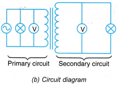
- It is made up of two coils wound on a soft iron core as shown in Figure.
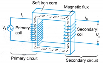
- The primary coil is connected to the a.c. power supply while the secondary coil is connected to the output terminals.
- When the current in the primary circuit increases, the growth of the magnetic flux causes the magnetic field lines to cut the secondary coil. An e.m.f. is induced in the secondary coil.
- When the current in the primary circuit decreases, the magnetic flux collapses and the field lines again cut the secondary coil. An e.m.f. acting in the opposite direction is induced in the secondary coil.
- The alternating current in the primary coil produces a changing magnetic flux that induces an alternating e.m.f. of the same frequency in the secondary coil.
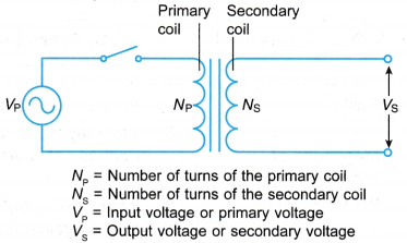
- Figure shows the circuit diagram for a transformer with an alternating power supply.
People also ask
- What are the Losses in a Transformer?
- What is the electromagnetic induction?
- What is magnetic force on a current carrying conductor?
- What factors affect the strength of an electromagnet?
- What is the Meaning of Magnetic Force?
- What Is Magnetic Effect Of Electric Current?
- Oersted Experiment on Magnetic Effect of Current
- How do you Determine the Direction of the Magnetic Field?
What are the different types of transformers?
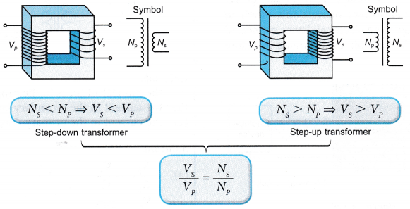
Step-up and Step-down Transformers:
- There are two types of transformers:
(a) The step-up transformer
(b) The step-down transformer - Figure gives the comparison between the two types of transformers.
Step-up and Step-down Transformers Experiment
Aim: To understand a step-up and a step-down transformer.
Materials: 120-turn copper coil, 400-turn copper coil, connecting wires
Apparatus: Two C-shaped iron cores with clip, insulated wires, low voltage a.c. power supply, two 2.5 V 0.3 A bulbs with holders and two 6.2 V 0.3 A bulbs with holders
Method: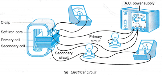
Step-up Transformer
- The apparatus is set up as shown in Figure. The primary coil is the 120-turn copper coil and the secondary coil is the 400-turn copper coil.
- The 6.2 V, 0.3 A bulbs are screwed into the respective holders.
- The power supply is set to 2 V a.c.
- The power supply is switched on. The brightness of the bulbs in the primary and secondary circuits are compared.
Step-down Transformer
- The set up of the apparatus is changed so that the 400-turn copper coil becomes the primary coil and the 120-turn coil is the secondary coil.
- The bulbs are replaced with 2.5 V, 0.3 A bulbs.
- The power supply is switched on. The brightness of the bulbs in the primary and secondary circuits are compared.
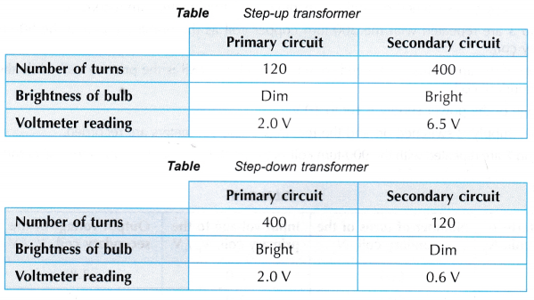
Observations:
 Discussion:
- The brightness of the bulb is proportional to the voltage across it. The brightness of the bulb in the primary circuit indicates the magnitude of the input voltage. The brightness of the bulb in the secondary circuit indicates the magnitude of the output voltage.
- When the number of turns of the secondary coil is more than the primary coil, the output voltage is greater than the input voltage.
- When the number of turns of the secondary coil is less than the primary coil, the output voltage is smaller than the input voltage.
Conclusion:
- A higher voltage is induced in the secondary coil when the secondary coil has more turns than the primary coil.
- A lower voltage is induced in the secondary coil when the secondary coil has less turns than the primary coil.
Relationship between Turns Ratio and Voltage Ratio Experiment
Aim: To show the relationship Vs/Vp = Ns/Np
Materials: Copper coils with 300, 600 and 900 turns respectively, connecting wires
Apparatus: Soft iron cores, 0 – 12 V a.c. power supply, two a.c. voltmeters (0 – 10 V)
Method: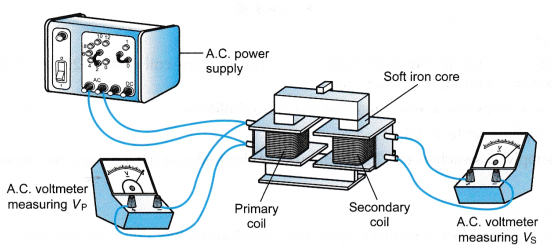
- The apparatus is set up as shown in Figure with the 300-turn copper coil as the primary coil and the 600-turn coil as the secondary coil.
- The voltage of the power supply is set at 2 V.
- The power supply is switched on and the readings of the voltmeters are recorded.
- Steps 1 to 3 are repeated with the 300-turn copper coil as the primary coil and the 900-turn coil as the secondary coil.
- The set up of the apparatus is changed so that the 900-turn coil is the primary coil while the 600-turn coil is the secondary coil.
- The voltage of the power supply is set to 10 V.
- The power supply is switched on and the readings of the voltmeters are recorded.
- Steps 6 and 7 are repeated with the 900-turn coil as the primary coil and the 300-turn coil as the secondary coil.
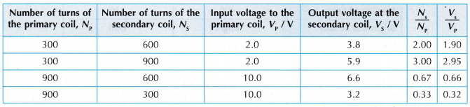
Observations:
Discussion:
- The ratios Ns/Np and Vs/Vp for each pair of primary and secondary coils are approximately equal.
- Taking into account experimental errors and the loss of power in the transformer, it can be inferred that Ns/Np = Vs/Vp.
Conclusion:
The ratio of the secondary output voltage to the primary input voltage is equal to the ratio of the number of turns in the secondary coil to the number of turns in the primary coil.
Turns Ratio and Voltage Ratio Problems with Solutions
- Figure shows a 12 V bulb connected to the output terminals of a transformer.
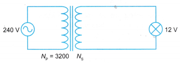
What is the value of Ns if the bulb were to light up at normal brightness?
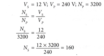
Solution:
When the bulb lights up at normal brightness, the voltage across it is 12 V.
Relationship between Output Power and Input Power of an Ideal Transformer
- A transformer transfers electrical power from the primary circuit to the secondary circuit.
- The primary circuit of a transformer receives power at a certain voltage from the a.c. power supply. The transformer delivers this power at another voltage to an electrical device connected to the secondary circuit, as illustrated in Figure.
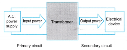
- In an ideal transformer, there are no energy losses during the process of transforming the voltage and transfer of power.
- The output power is equal to the input power. Therefore,
Output power = Input power
That is:

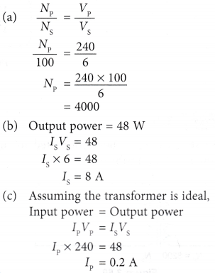
Transformer Primary and Secondary Current Calculation
Figure shows a transformer being used to operate a 6 V, 48 W heater from a 240 V a.c. supply.
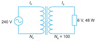
Calculate
(a) the number of turns in the primary coil, Np
(b) the current in the secondary coil, Is
(c) the current in the primary coil, Ip
Solution: