What is magnetic force on a current carrying conductor?
The Force on a Current Carrying Conductor in a Magnetic Field
- Figure shows the power window of a car. The glass sheet can slide up or down when the switch is pulled.
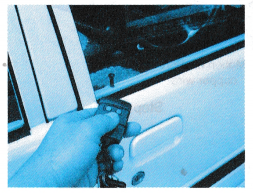
- The movement of the glass sheet is produced by an electric motor in the door of the car.
- In an electric motor, forces are exerted on coils that carry current in a magnetic field.
- Electrical meters such the ammeter and voltmeter in the laboratory also make use of the force on a current-carrying conductor.
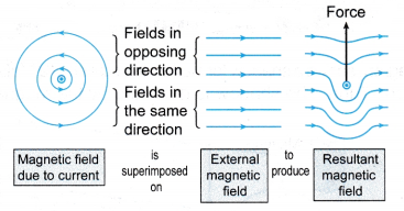
- The force on a current-carrying conductor in a magnetic field is due to the resultant magnetic field produced by the combination of
(a) the magnetic field due to the current in the conductor
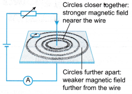
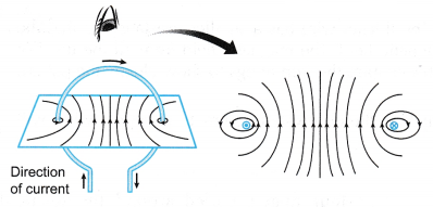
(b) and an external magnetic field due to the permanent magnets. - The resultant magnetic field has magnetic field lines that are stretched round the conductor. It is known as a catapult field.
- The magnetic field is stronger on one side of the conductor than on the other side. This causes a resultant force to act on the conductor, as shown in Figure.
People also ask
- Factors Affecting the Magnitude of the Force on a Current-carrying Conductor
- What is the Meaning of Magnetic Force?
- What factors affect the strength of an electromagnet?
- How Does a Transformer Work?
- What is the Magnetic Field?
- What Is Magnetic Effect Of Electric Current?
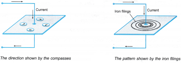
- Oersted Experiment on Magnetic Effect of Current
- How do you Determine the Direction of the Magnetic Field?
- Who discovered the magnet?
- How does a magnet work?
- What are the Different Types of Magnets?
- Is an electromagnet a temporary or a permanent magnet?
- What is the use of magnet?
- How does an electric bell work using electromagnets?
The Direction of the Magnetic Force
- The direction of the force can be determined using Fleming’s left-hand rule.
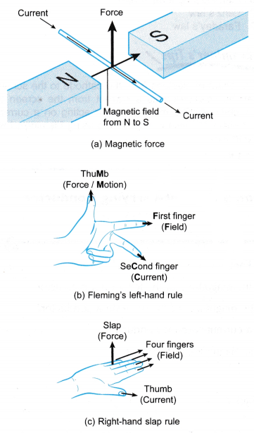
- The following steps are used, as shown in Figure (b):
(a) Point the first finger of the left hand in the direction of the magnetic field from the North pole towards the South pole.
(b) The left hand is then rotated so that the second finger points in the direction of the current.
(c) The thumb indicates the direction of the magnetic force. This is also the direction of motion if the conductor is free to move. - Another rule that can be used is the right-hand slap rule, as shown in Figure (c):
(a) Point the four fingers of the right hand in the direction of the field.
(b) Rotate your hand until the thumb points in the direction of the current.
(c) Do a slapping action. The direction of the slap is the direction of the magnetic force.
Magnetic Force on a Current Carrying Conductor Experiment
Aim: To study the magnetic force acting on a current-carrying conductor.
Materials: Bare copper wires (s.w.g. 20 or thicker) two thumbtacks, a pair of magnadur magnets, U-shaped steel yoke, wooden block, connecting wires
Apparatus: Low voltage d.c. power supply
Method: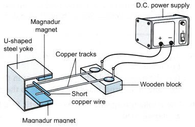
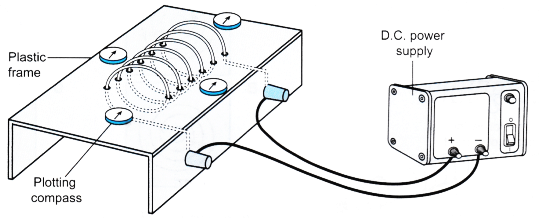
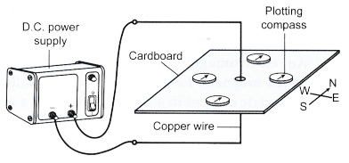
- The apparatus is set up as shown in Figure.
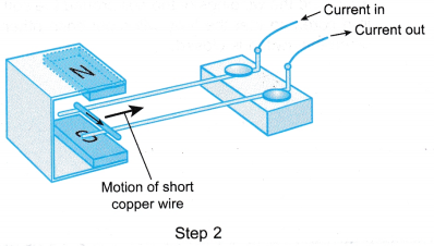
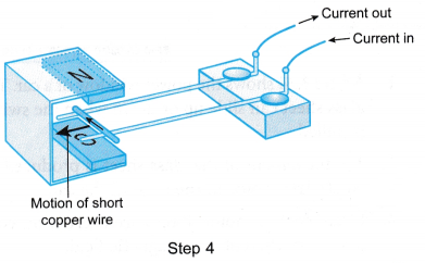
- The d.c. power supply is switched on and the motion of the short copper wire is observed.
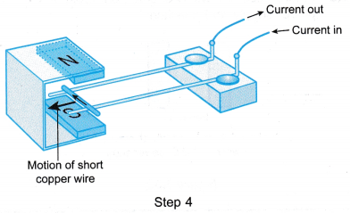
- The power supply is switched off and the connections to the power supply are interchanged.
- The power supply is switched on again and the motion of the short copper wire is observed.
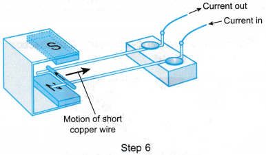
- The power supply is switched off and the U-shaped steel yoke with the magnadur magnets is inverted.
- The power supply is switched on and the motion of the short copper wire is observed.
Observations:
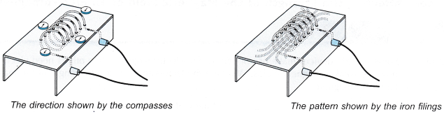
- The observation in Step 2 and Step 4 are as shown in Figure.
- The observation in step 4 and step 6 are as shown in Figure.
Discussion:
- Before the power supply is switched on, there is a magnetic field between the magnadur magnets.
- The current in the short copper wire produces a magnetic field around the wire.
- The motion of the short copper wire shows that a force is exerted on the wire.
- The force on the wire is due to the interaction between the magnetic field due to the magnadur magnets and the magnetic field due to the current in the wire.
- When the connections to the power supply were interchanged, the current in the short copper wire changes direction. This causes the direction of the force on the wire to change.
- The direction of the magnetic field is from the North pole to the South pole. A change in the direction of the magnetic field causes a change in the direction of the force.
Magnetic Force on a Current Carrying Conductor Examples
- Figure shows the set-up of apparatus to study a current-carrying conductor in a magnetic field.
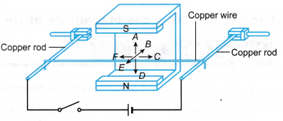
(a) State the direction of the magnetic field.
(b) When the switch is closed, state the direction of
(i) the current,
(ii) the motion of the copper wire.
Solution:
(a) A
(b) (i) C (ii) E - Figure shows a current-carrying wire between the poles of a pair of permanent magnets.
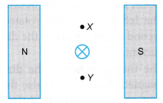
(a) State the direction of the magnetic field due to the permanent magnets.
(b) Describe the magnetic field pattern produced by the current.
(c) Compare the strength of the resultant magnetic field at point X and point Y.
(d) State the direction of the magnetic force on the wire.
Solution:
(a) From North to South
(b) Concentric circles in a clockwise direction
(c) Magnetic field at X is stronger
(d) Downwards
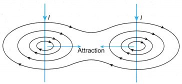 (b) Figure shows the magnetic field for two straight parallel wires carrying current in opposite directions. The wires repel with each other.
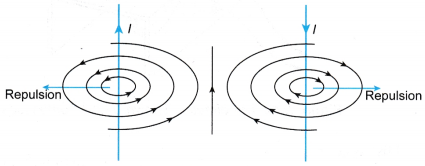
 Discussion:
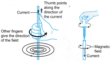
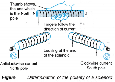 (a) Using the right-hand grip rule. Hold the solenoid using your right hand with your four fingers curled around the solenoid along the direction of the current. The thumb will point to the end that is the North pole.