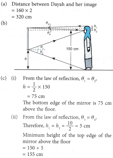
What is Reflection of Light?
Light rays travel in a straight line. A ray is a very narrow beam of light.
An object can only be seen when light rays from the object enter our eyes. These light rays can come directly from the object or as a result of the object reflecting light rays from a light source.
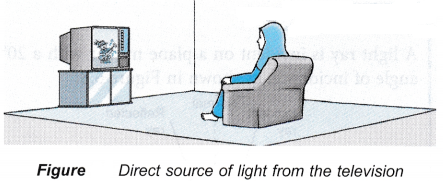 (a) The pictures from the television can be seen because the television emits light.
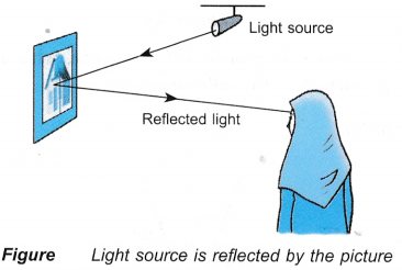 (b) The picture can be seen because it reflects light from the light source.
Definition: When light rays are incident on an opaque polished surface (medium), these are returned back in the same medium. This phenomenon of returning of ray of light in the same medium, is called reflection of light.
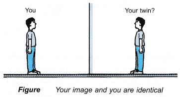
When you look at a mirror, you see the reflection of other things around you along with your own image.
People also ask
Definition of some associated terms:
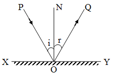
- Reflecting surface: The surface from which the light is reflected, is called the reflecting surface. In diagram, XY is the reflecting surface.
- Point of incidence: The point on the reflecting surface at which a ray of light strikes, is called the point of incidence. In diagram, O is the point of incidence.
- Normal: A perpendicular drawn on the reflecting surface at the point of incidence, is called the normal. In diagram, ON is the normal.
- Incident ray: The ray of light which strikes the reflecting surface at the point of incidence is called the incident ray. In diagram, PO is the incident ray.
- Reflected ray: The ray of light reflected from the reflecting surface from the point of incidence, is called the reflected ray. In diagram, OQ is the reflected ray.
- Angle of incidence: The angle that the incident ray makes with the normal, is called the angle of incidence. It is represented by the symbol i. In diagram, angle PON is the angle of incidence.
- Angle of reflection: The angle that the reflected ray makes with the normal, is called the angle of reflection. It is represented by the symbol r. In diagram, ∠QON is the angle of reflection.
- Plane of incidence: The plane in which the normal and the incident ray lie, is called the plane of incidence. In diagram, the plane of the bookpage, is the plane of incidence.
- Plane of reflection: The plane in which the normal and the reflected ray lie, is called the plane of reflection. In diagram, the plane of the book page, is the plane of reflection.
Reflection of Light on a Plane Mirror
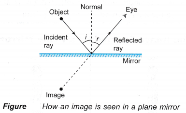
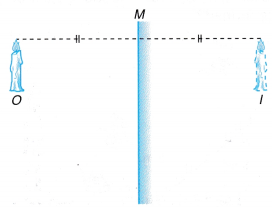
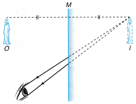
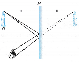
- When you look at the image of an object in a plane mirror, the rays of light originating from the object hit the mirror and bounce or reflect from the mirror towards your eye. These reflected rays produce the image that is seen in the mirror.
- The ray of light that strikes the mirror is known as the incident ray. The ray of light which reflects from the mirror is known as the reflected ray.
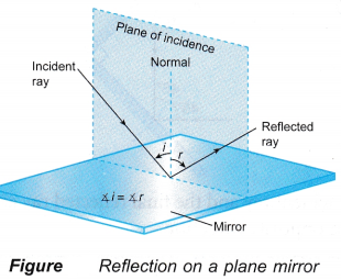
- The normal is a line drawn perpendicularly (at a right-angle) to the surface of the reflector. The normal line divides the angle between the incident ray and the reflected ray into two equal angles.
- The angle between the incident ray and the normal is known as the angle of incidence (i). The angle between the reflected ray and the normal is known as the angle of reflection (r).
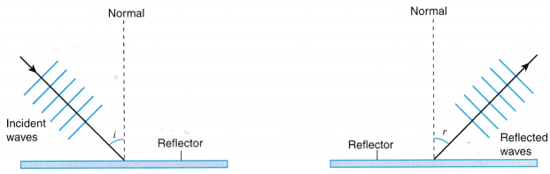
Note: The angles of incidence and reflection are always measured from the normal. - The behaviour of light when it is reflected follows a law known as the law of reflection.
- The incident ray, the reflected ray and the normal to the surface lie in the same plane.
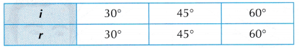
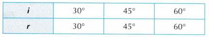
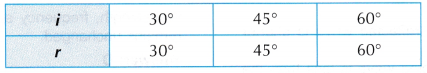
- The angle of incidence is equal to the angle of reflection (∠i = ∠r).
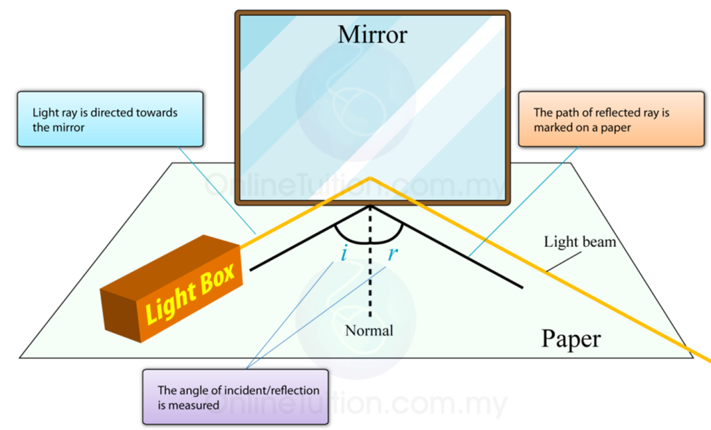
Reflection of Light Experiment
Aim: To study the nature of reflection.
Materials needed: A4 size paper, a pair of scissors, adhesive tape, and a wall mirror (bathroom mirror, dressing mirror, etc.)
Method:
- Fold the A4 size paper in the middle, lengthwise.
- Cut out a thin slit on the fold, leaving out 1 inch on the top and bottom of the paper.
- Open out the paper and stick it on a mirror.
- Look at yourself in the mirror through the slit in the paper. Make a note of the various objects that you can see behind you.
- Now move to your right and look at the mirror through the slit. Try out various positions. Try to see along the surface of the mirror. Make a note of the images that you see at the various positions of your eye.
Observation: You will notice that you will be able to see yourself only if you are directly in front of the slit. If you move to the right, you will be able to see the image of things to your left. If you move further to the right, you will be able to see things further to your left.
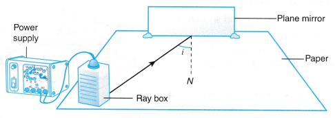
Let us put down our observations from the above activity in a scientific manner, by drawing a diagram. First draw a line perpendicular (i.e., a line that makes an angle of 90°) to the mirror at the point where the slit is located. This line, SN, is called the normal.
The rays of light that come from the object and hit the mirror are called incident rays. In figure, AS and BS are incident rays. The rays of light that get reflected from (i.e., bounce off) the mirror are called reflected rays. In figure, SA’ and SB’ are reflected rays.
The point at which the incident ray hits the mirror is called the point of incidence. In figure, S is the point of incidence. A normal drawn to the mirror at the point of incidence is called a normal at the point of incidence. The angle between the incident ray and the normal is called the angle of incidence. In figure, angle ASN is the angle of incidence of the incident ray AS. The angle between the reflected ray and the normal is called the angle of reflection. In figure, the angle of reflection of the reflected ray SA’ is NS A’.
Refraction of Light Problems with Solutions
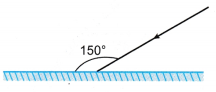
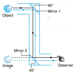
- Two plane mirrors are placed at right angles to each other as shown in Figure. A light ray is incident on one of the mirrors at 45°. Complete the path of the light ray in the figure. What can you say about the path of the incident ray and the final reflected ray?
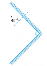
Solution:
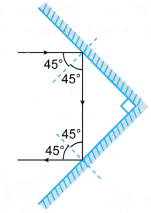
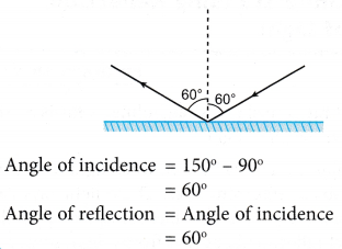
The incident ray and the final reflected ray are parallel but in opposite direction. - Figure shows a light ray incident on mirror.
What is the angle of reflection?
Solution:
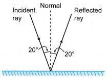
- A light ray is incident on a plane mirror with a 20° angle of incidence, as shown in Figure.
If the mirror is rotated 10° clockwise, what is the angle turned by the reflected ray?
Solution:
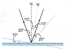
The angle turned by the reflected ray = 20°
Note: The angle turned by reflected ray is always ^twice the angle turned by the plane mirror.
Reflecting Surfaces
All types of surfaces reflect light. That is why we can see them. When light from the sun or any source falls on an object, we are able to see the object because the light reflected by the object reaches our eyes.
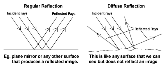
While talking of reflection, we refer to a smooth surface as a regular surface, and a rough and wavy surface as an irregular surface. A regular surface reflects light in only one direction. Reflection by a regular surface is referred to as regular reflection. A rough surface reflects a parallel beam of light incident upon it in all directions. The small bumps and irregularities on a rough surface cause each of the light rays to reflect in different directions. This kind of reflection is called irregular or diffused reflection.
Reflecting Surfaces Activity
Aim: To observe reflection from different types of surfaces.
Materials needed: Glass, metal sheet, metal foil, white paper, and mirror.
Method:
- Take each object and stand in front of a sunlit window.
- Try to catch the rays of the sun on the object and project it onto a wall.
What are the different kinds of images formed? Record your observations for each object.
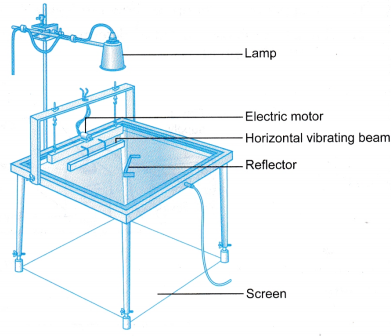
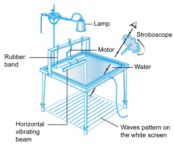 (a) When a steady train of waves move across the water surface, each wave crest acts like a convex lens and concentrates the light on the screen as shown in Figure. Flence, a bright pattern on the screen corresponds to a crest of the waves.
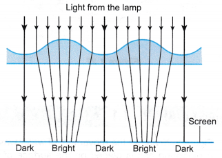 (b) A stroboscope is normally used to observe wave patterns on the screen. By rotating the stroboscope at the same frequency as the motor of the ripple tank kit, the motion of the waves can be frozen for more detailed observation.
 Discussion:
 Discussion: