What is the electromotive force of a cell?
- A light bulb will light up when it is connected in series with a cell as shown in Figure.
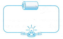
- The cell is the source of energy and the bulb is the energy-consuming device.
- The light bulb converts electrical energy into heat and light energy.
- The electric charges that flow around the circuit transfer energy from the source to the device.
- In a cell, chemical reactions convert chemical energy into electrical energy. This energy pushes the free electrons to move from the negative terminal to the positive terminal of the cell.
What do you mean by electromotive force?
Work is done by the source in driving the charges around a complete circuit. This work done is known as electromotive force.
The electromotive force (e.m.f.) is the work done by a source in driving a unit of charge around a complete circuit.
People also ask
- What is Electric Current?
- What is an electric field and how is it created?
- What is the Relationship between Electric Current and Potential Difference?
- How series and parallel circuits are different?
- Relationship between Energy Transferred, Current, Voltage and Time
- Power Rating and Energy Consumption of Various Electrical Appliances
What is the difference between potential difference and electromotive force?
Electromotive Force and Potential Difference
- The definition for electromotive force (e.m.f.) is similar to that of potential difference (p.d.).
However, there is a distinction between e.m.f. and p.d. - The e.m.f. of a cell is the energy supplied to a unit of charge within the cell.
- The p.d. across a component in a circuit is the conversion of electrical energy into other forms of energy when a unit of charge passes through the component.
- When the switch is open as shown in Figure, the circuit is called an open circuit.
- The reading of the ammeter is zero as there is no current flow in an open circuit. The voltmeter gives a reading showing that the voltmeter measures the potential difference across the cell in an open circuit.
- Therefore the e.m.f. of a cell can also be defined as the potential difference across the cell in an open circuit.
- When the switch is closed, the circuit is a closed circuit and current flows in the circuit. The ammeter gives a reading. The voltmeter’s reading drops a little and this gives the potential difference across the terminals of the cell.
- Therefore in a closed circuit, the potential difference across the cell is also known as the terminal potential difference.
What is meant by the internal resistance of a cell?
- In an open circuit when there is no current flow, the potential difference, V across the battery is the electromotive force, E of the battery.
- In a closed circuit, when there is a current flow in the circuit, the potential difference, V across the cell is smaller than the electromotive force, E of the cell.
- This drop in potential difference across the cell is caused by the internal resistance of the cell.
- The internal resistance of a source or cell is the resistance against the moving charge due to the electrolyte in the cell.
- Work is done to drive the charge against the internal resistance.
- This causes a drop in potential difference across the battery as charges flow through it.
What is internal resistance in a circuit?
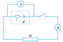
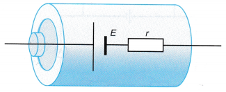
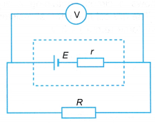
- A battery can be modelled as an e.m.f., E connected in series with an internal resistor, r as shown in Figure.
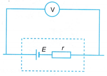
- When a high-resistance voltmeter is connected across the terminals of the battery as shown in Figure 2.52, the reading of the voltmeter gives the e.m.f. of the battery.
- If a resistor, R is now connected to the terminals of the battery as shown in Figure, the voltmeter reading is the potential difference, V across the resistor, R. It is also the terminal potential difference across the terminals of the cell.
- The value of the potential difference, V is less than the e.m.f., E of the cell. The difference between E and V is due to the potential difference needed to drive the current, I through the internal resistance, r of the battery.
Hence,
E – V = Ir ⇒ E = V + Ir
Where,
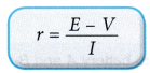
e.m.f. = Potential difference + Drop in potential difference due to internal resistance - The internal resistance, r is given by:
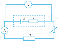
- If the rheostat in Figure is varied for a set of values for the current, I and the terminal potential difference, V, a graph of V against I can be plotted to get the values of e.m.f., E and internal resistance, r.
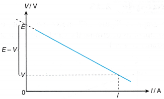
- The graph of V against I in Figure is a straight line graph.
 The straight line can be represented by the equation:
V = -rI + E [from E – V = Ir] - If the straight line is extrapolated until it cuts the vertical axis, V, the values of I = 0 and V = E are obtained. This shows that when no charges flow, the potential difference across the cell is the electromotive force.
- The gradient of the graph is negative showing that V is always less than E by some quantity of Ir. The value of Ir is sometimes called the ‘lost voltage’ due to the internal resistance, r.
- The internal resistance, r can be determined from the gradient of the graph.
Electromotive Force and Internal Resistance Sample Problems with Solutions
- Figure shows a circuit which consists of a battery connected in series with a 10.0 Ω resistor. The potential difference across the resistor is measured as 2.5 V.
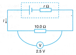
If the internal resistance of the battery is given as 2.0 Ω, find the e.m.f. of the battery.
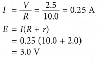
Solution:
- The graph in Figure shows the results of an experiment to determine the e.m.f. and the internal resistance of a cell.
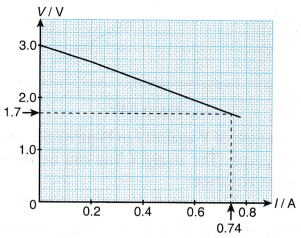
From the graph, determine the e.m.f. of the cell and its internal resistance.
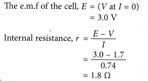
Solution:
Internal Resistance of a Dry Cell Experiment
Aim: To study internal resistance.
Apparatus: Two dry cells, switch, bulb, voltmeter, rheostat, 2 Ω. resistor, connecting wires
Method:
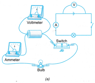
- The electrical circuit is set up as shown in Figure (a).
- The reading of the e.m.f., E on the voltmeter when the switch is open is recorded.
- The switch is closed and the readings of the potential difference, V and current, I are recorded.
- The brightness of the bulb is observed.
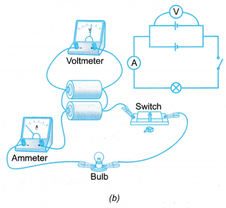
- Steps 2 to 4 are repeated by connecting two cells in parallel as shown in Figure (b).
- The observations are recorded in a table.
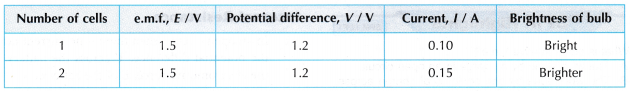
Observations:
Discussion:
- The value of the potential difference, V is smaller than the value of the e.m.f., E due to the internal resistance of the cell.
- When there are two cells connected in parallel, the value of e.m.f. in the two cells remain the same as the e.m.f. of a single cell. This is because the two cells connected in parallel are sharing terminals. Therefore the e.m.f. of the cells remain the same.
- When there are two cells connected in parallel, the value of the potential difference of the two cells remain the same as the potential difference of a single cell.
- The brightness of the bulb increases when there are two cells connected in parallel because the current flow through the bulb is larger due to the small effective internal resistance of the cells connected in parallel.
- Cells connected in parallel can last longer as more energy can be stored in the cells.
- In other words, we can conclude that the differences between e.m.f. and potential difference are:
(a) The e.m.f. of a cell is the maximum electrical energy available per coulomb.
(b) The potential difference of a bulb in a circuit is the electrical energy that can be used per coulomb. - Figure shows a voltmeter connected across a battery in an open circuit.
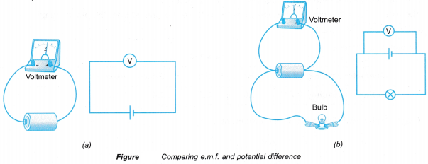
- The voltmeter measures the electrical energy that is supplied to a coulomb of charge that passes through the cell. This is the potential difference across the cell in the open circuit when there is no current flow in the circuit. This potential difference is the e.m.f. of the cell.
- In Figure (b), the voltmeter is connected to the same cell in a closed circuit.
- The value of potential difference, V is smaller than the value of e.m.f., E. This is due to the energy dissipated in the cell when 1 C of charge passes through it.
- A voltmeter measures the energy dissipated by 1 C of charge that flows through any devices connected in the circuit.
- The SI unit for e.m.f. is the same as for potential difference. Both are measured in volts (V).
EMF and Internal Resistance of a Dry Cell Experiment
Aim: To determine the e.m.f. and the internal resistance of a battery.
Apparatus: Two dry cells, switch, ammeter, voltmeter, rheostat, 2 Ω resistor, connecting wires
Method:
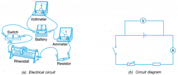
- The electrical circuit is set up as shown in Figure.
- The switch is closed and the rheostat is adjusted until the ammeter reading has reached the minimum value. The ammeter reading and the corresponding voltmeter reading are recorded.
- Step 2 is repeated by adjusting the rheostat to get five sets of readings with increasing current.
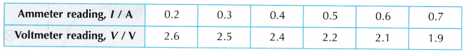
- All the readings are recorded in a table.
- A graph of potential difference, V against current, I is plotted.
- The e.m.f., E and the internal resistance, r of the cell are determined from the plotted graph.
Results:
- Tabulation of results.
- Graph of potential difference, V against current, I.
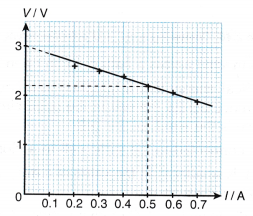
- The e.m.f., E is determined by extrapolating the straight line graph. The value of the potential difference, V at current, I = 0 A is the e.m.f. of the cell. From the graph, the e.m.f., E of the cell is 3.0 V.
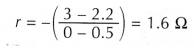
- The internal resistance, r of the cell is determined from the gradient of the graph, where r is the negative of the gradient of the graph.
Discussion:
- The increase of the current, I in the circuit results in more energy being dissipated by the internal resistance, r of the cell. The portion of the energy, supplied by the cell, that is given to the circuit becomes smaller. Thus, the potential difference, V is decreasing.
- The purpose of resistor R in the circuit is to reduce the current flow and to avoid a short circuit when the resistance of the rheostat becomes low. Low resistance in a circuit will result in large current flow. This will spoil the ammeter which is connected in series.
EMF and Potential Difference of a Dry Cell Experiment
Aim: To distinguish between e.m.f. and potential difference.
Apparatus: Dry cells, switch, bulb, voltmeter, connecting wires
Method:
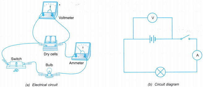
- The electrical circuit is set up as shown in Figure.
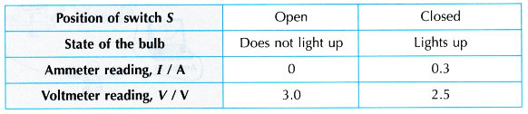
- Switch S is left in open position. What happens to the bulb is observed. The readings of the ammeter and the voltmeter are recorded.
- Switch S is closed. What happens to the bulb is observed. The readings of the ammeter and the voltmeter are recorded.
Observation:
Discussion:
- The reading of the voltmeter when switch S is open is higher than when switch S is closed.
- The reading of the voltmeter when the circuit is open is the e.m.f. value of the cell. From the observation in Table, the voltmeter reading is 3.0 V when switch S is open. Therefore 3 J of electrical energy is required to move 1 C of charge across the cell.
- The reading of the voltmeter when the circuit is closed is the potential difference across the bulb. From the observation in Table, the voltmeter reading is 2.5 V when switch S is closed. Therefore, 2.5 J of electrical energy is dissipated by 1 C of charge after passing through the bulb. The electrical energy is transformed to light and heat energy.