ICSE Solutions for Class 10 Physics – Magnetic Effect of Current
ICSE SolutionsSelina ICSE Solutions
APlusTopper.com provides ICSE Solutions for Class 10 Physics Chapter 9 Magnetic Effect of Current for ICSE Board Examinations. We provide step by step Solutions for ICSE Physics Class 10 Solutions Pdf. You can download the Class 10 Physics ICSE Textbook Solutions with Free PDF download option.
Download Formulae Handbook For ICSE Class 9 and 10
Short Answers
Question 1: State whether a magnetic field is associated or not around (i) a static charge, (ii) a moving charge; (iii) current carrying conductor.
Answer: (i) A static charge is not associated with a magnetic field around it.
(ii) A moving charge is associated with a magnetic field around it.
(iii) A current carrying conductor is associated with a magnetic field around it.
Question 2: What is the nature of the lines of force of the magnetic field due to a straight current carrying wire?
Answer: The lines of force, in this case, are concentric circles centered on the wire.
Question 3: What will happen to a compass needle when the compass is placed below a wire and a current is made to flow through the wire? Give a reason to justify your answer.
Answer: The compass needle will show deflection. This happens because when a current is passed through a conductor (here, wire) a magnetic field is produced around the conductor due to which the compass needle gets deflected.
Question 4: State two factors on which the strength of induced e. m.f. depends.
Answer: (i) The time of change of magnetic flux, (ii) The strength of magnetic field.
Question 5: Describe briefly one way of producing an induced current in a coil. State one factor that determines the magnitude of induced e.m.f.
Answer: To produce an induced current in a coil, a magnet is moved along the axis of coil.
The magnitude of induced e.mi. depends on the strength of magnet.
Question 6: State the two properties of the magnetic lines of force around a circular coil.
Answer: The important properties are:
(i) The magnetic lines of force near the wire are nearly circular, especially at the points where
the current enters or leaves the coil.
(ii) At the centre of the coil, the lines of force are almost parallel to each other, showing that the magnetic field at the centre or the coil may be considered uniform.
Question 7: A straight wire is held vertical and current is passed in it in the upward direction. A compass needle is kept near the wire in north of it. How is the needle deflected? What is the change in the deflection of the needle if the current in wire is reversed?
Answer: When the current in the wire is upwards, the needle will deflect with its north pole towards west.
If the current in the wire is reversed, the north pole of the needle will deflect towards east.
Question 8: Describe a simple Experiment to demonstrate that there Exists a magnetic field around a current carrying conductor.
Answer: The conductor is kept in N-S direction and its ends are connected to a battery, rheostat and a tapping key. When the key is open i.e., no current flows in the conductor, the needle points in N-S direction. As the key is pressed and a current passes in the conductor, the needle deflects. This shows that a magnetic field Exists around a current carrying conductor.
Question 9: State the law which determines the direction of magnetic field round a current carrying conductor.
Answer: The direction of magnetic field produced due to flow of current in a conductor can be determined by the right hand thumb rule. It states that if we hold the current carrying conductor in our right hand such that the thumb points in fire direction of current then the fingers encircling the wire indicate the direction of the magnetic lines of force.
Question 10: A straight current carrying conductor is kept in a magnetic field. It Experiences a force. State three factors on which the magnitude of force Experienced by the conductor depends. Under what condition will the conductor Experience no force?
Answer: The three conditions are: (i) Current in the conductor, (ii) Length of conductor, (iii) Strength of i magnetic field. The conductor will Experience no force if the direction of current in the conductor is parallel to the direction of magnetic field.
Question 11: State under what conditions force acting on a current carrying conductor which is freely suspended in a magnetic field can be (i) maximum (ii) Zero.
Answer: (i) This force F is maximum when the magnetic field due to flow of current in the conductor and the given magnetic field B are perpendicular to each other.
(ii) This force F is zero when the magnetic field due to flow of current in the conductor is parallel to the given magnetic field B.
Question 12: State the purpose of the iron core.
Answer: The purpose of the iron core is to intensify the strength of the magnetic field inside the
solenoid and thereby increase the strength of the electromagnet.
Question 13: How does a magnetic field set up by a solenoid change when number of turns are increased?
Answer: By having more number of turns, the intensity of magnetic field increases.
Question 14: How does a magnetic field set up by a solenoid change when cross-sectional area of solenoid is increased?
Answer: By having a solenoid of large diameter or more cross-sectional area, the intensity of magnetic field increases.
Question 15: How does a magnetic field set up by a solenoid change when a soft iron core is inserted inside solenoid?
Answer: By placing a soft iron core inside the solenoid, the magnetic field becomes more intense.
Question 16: How does a magnetic field set up by a solenoid change when strength of current in the solenoid is decreased?
Answer: By decreasing the current flowing in the solenoid, the intensity of magnetic field decreases.
Question 17: State two ways by which the magnetic field of a solenoid can be made stronger.
Answer: (i) By increasing current. (ii) By increasing no. of turns.
Question 18: Why is soft iron generally used as the core of the electromagnet?
Answer: (i) Soft iron has less retentivity so it acquires the magnetic properties only when the current flows through the coil wound on it and loses the magnetic properties as the current is switched off.
(ii) The soft iron intensifies the magnetic field of the electromagnet because of its high permeability.
Question 19: Name two factors on which the magnitude of an induced e.m.f. in the secondary coil depends.
Answer: Magnitude of induced e.m.f. depends on
(i) Magnitude of current. (ii) No. of turns in the coil.
Question 20: What is an electromagnet?
Answer: An electromagnet is a solenoid containing a soft iron core within it. It is a temporary strong magnet. It acquires the magnetic properties only when an electric current flows through the solenoid and loses the magnetic properties as the current is switched off.
Question 21: State the condition when an electric charge can give rise to a magnetic field.
Answer: When an electric charge flows in a conductor, a magnetic field is produced around it.
Question 22: List some of the practical applications of an electromagnet.
Answer: Electromagnets are used to lift heavy loads of scrap iron etc., to separate magnetic substances from non-magnetic ones and in devices like the electric bell, telegraphs, telephones, loud speakers, etc.
Question 23: What is a permanent magnet? Give one use of it.
Answer: A permanent magnet is a magnet made from steel such that once magnetised, does not lose its magnetism easily.
Use: It is used in galvanometer.
Question 24: State two advantages of an electromagnet over a permanent magnet.
Answer: The two advantages are:
(i) An electromagnet can produce a strong magnetic field and its strength can be controlled by changing the strength of the current or the number of turns in the coil.
(ii) The polarity of an electromagnet can be changed by reversing the direction of current that flows in the solenoid.
Question 25: State two advantages of an electromagnet over a bar magnet.
Answer: Electromagnet can produce a strong magnetic field. Its polarity can be changed by reversing the direction of current.
Question 26: What will be the effect on the working of an electric bell if instead of a direct current an alternating current is used?
Answer: If electric bell is connected to a.c. instead of d.c. then bell will ring intermittently.
Question 27: Name a common device that uses electromagnets.
Answer: Electromagnets are used in electric bell, door alarm, motor, dynamo etc.
Question 28: What material is used for making the armature of an electric bell? Give a reason for using this material.
Answer: A soft iron metal piece is used for making the armature of an electric bell.
Reason: Soft iron can be easily magnetised.
Question 29: What is an electric motor? State its principle.
Answer: An electric motor is a device which converts the electrical energy into the mechanical energy.
The working of an electric motor is based on the principle that a current carrying coil placed in a magnetic field with its plane parallel to the field, Experiences a deflecting couple.
Question 30: State three factors which govern the speed of rotation of an electric motor.
Answer: (i) The strength of current in the coil, (ii) The number of turns in the coil, (iii) The strength of the magnetic field.
Question 31: How will the direction of force be changed if the current is reversed in the conductor placed in a magnetic field?
Answer: The direction of force will be reversed.
Question 32: State the unit of magneitc field in terms of force Experienced by a current carrying conductor placed in a magnetic field.
Answer: Newton/(ampere-metre) or NA-1 m-1.
Question 33: What energy conversion takes place during the working of a d c motor?
Answer: Electrical energy to mechanical energy.
Question 34: State the factors that can increase the speed of rotation of the coil in a D.C. motor.
Answer: The speed of rotation of the coil in a D.C. motor can be increased by:
(i) Increasing the strength of the current, (ii) Having more turns in the coil,
(iii) Increasing the area of the coil, (iv) By increasing the strength of the magnetic field.
Question 35: State the energy change that takes’place in a D. C. motor.
Answer: The energy change that takes place in a D. C. motor is from electrical energy into mechanical energy.
Question 36: State the principle of a D. C. motor.
Answer: It is based on the principle that when an electric current is passed through a conductor placed normally in a magnetic field, a force acts on the conductor as a result of which the conductor begins to move. The direction of the force is obtained with the help of Fleming’s left hand rule.
Question 37: State the position of armature coil relative to the direction of magnetic field, in a D. C. motor when the deflecting couple acting an the coil is (i) maximum, (ii) minimum.
Answer: (i) The deflecting couple acting on the coil is maximum when the plane of the coil is parallel to the direction of magnetic field.
(ii) The deflecting couple acting on the coil is minimum when the plane of the coil is normal to the direction of magnetic field.
Question 38: What do you understand by electromagnetic induction?
Answer: Whenever there is a change in number of magnetic lines of force associated with a coil, the e.m.f. induced in the coil lasts as long as the change takes place. This phenomenon is called electromagnetic induction.
Question 39: State Lenz’s law.
Answer: The Lenz’s law states that the direction of induced current is such that it opposes the cause which produces it.
Question 40: What is dynomo (a.c. generator)? State the principle on which it works.
Answer: Dynamo (or a.c. generator) is a device which converts mechanical energy into electrical energy. It works on the principle of electromagnetic induction.
Question 41: Suggest two ways in an a.c. generator to produce higher e.m.f.
Answer: (i) The speed of rotation of the coil is increased.
(ii) More powerful magnet is used to increase the strength of magnetic field.
Question 42: What is a transformer? On what principle does it work?
Answer: A transformer is device by which the amplitude of an alternating e.m.f. can be increased or decreased.
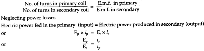
Question 43: How are the e.m.f. in the primary and secondary coils of a transformer related with the number of turns in these coils?
Answer:
![]()
Question 44: How do the input and output powers in a transformer compare?
Answer: In an ideal transformer, the output power is equal to. input power. But in an actual transformer, the output power is less than the input power.
Question 45: State the principle of a transformer.
Answer: It is based on the principle of ‘electromagnetic induction’. The magnitude of induced e.m.f. is given by the formula.
Question 46: Can a transformer be used with direct current source? Give reason.
Answer: No, a transformer cannot be used with direct current source. The reason is that with direct current source, there will not be any change in the magnetic flux linked with the primary coil, so no e.m.f. will be induced in the secondary coil.
Question 47: State the factors on which the frequency of the alternating e.m.f. depends.
Answer: The frequency of the alternating e.m.f. depends on the frequency of rotation of the coil.
Question 48: Name the principle on which functioning of a transformer depends.
Answer: The functioning of a transformer depends on the phenomenon of electromagnetic induction.
Question 49: What is the function of a step-up transformer?
Answer: We use a step-up transformer to push up or step up the voltage of a given a.c. source.
Question 50: Can a transformer work when it is connected to a D.C. source?
Answer: No, a transformer will not work with a D.C. source.
Question 51: Why is the core of a transformer made of soft iron?
Answer: The core of a transformer is made of soft iron because it has high permeability so it provides complete linkage of magnetic flux of the primary coil to the secondary coil. Secondly, the hysteresis loss of energy in soft iron is less.
Question 52: How do the input and output powers in a transformer compare?
Answer: In an ideal transformer, the output power is equal to input power. But in actual transformer the output power is less than the input power.
Question 53: Why is the core of a transformer laminated?
Answer: The core of a transformer is laminated to reduce the energy loss due to eddy currents.
Question 54: What energy conversion does take place in a generator?
Answer: The mechanical energy changes to electrical energy.
Question 55: The primary windings of a step-up transformer are usually made of thicker wire than the secondary. Explain.
Answer: In case of a step-up transformer, the e.m.f. across the secondary coil is greater than across the primary coil. So the current in the secondary coil is less than in the primary coil. Therefore to reduce heat loss in the windings, the primary coil is made of thicker wire than the secondary coil.
Long Answers
Question 1: State important properties (or characteristics) of magnetic lines of force around a straight conductor.
Answer: The main properties are:
(i) The magnetic lines of force are in the form of concentric circles around the conductor but as their distance from the conductor increases, the curvature of lines of force decreases.
(ii) The direction of the magnetic lines of force reverses, if the direction of flow of current in the conductor reverses.
(iii) With the increase of current in the conductor, the number of lines of force or the intensity of magnetic field also increases.
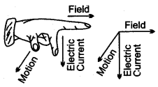
Question 2: Name and state the law which determines the direction of induced current.
Or
State Fleming’s right hand rule.
Answer: Fleming’s right hand rule: It states that if we stretch the thumb, the fore finger and the central finger of our right hand mutually perpendicular to each other such that the fore finger indicates the direction of magnetic field and the thumb indicates the direction of motion of conductor, then the central finger will indicate the direction of induced current.
Question 3: State the factors, on which depends the magnitude of the force acting on current carrying conductor, when it is kept in a magnetic field perpendicular to it.
Answer: Experimentally it is found that the magnitude of the force acting on a current carrying conductor kept in a magnetic field in a direction perpendicular to it, depends on the following factors:
(i) The F is directly proportional to the length of the current carrying conductor, i.e., F ∝ l.
(ii) F is directly proportional to the strength of the magnetic field, i.e., F ∝ B.
(iii) F is directly proportional to the strength of the current flowing in the conductor, i.e., F ∝ i.
Combining the above factors we find that:
or F ∝ i Bl
F = KiBl
Question 4: A current carrying solenoid is suspended so as to freely rotate in a horizontal plane. State in what direction will it rest. Give reason to your answer.
Or
When a solenoid that is carrying current is freely suspended, it comes to rest along a particular direction. Why does this happen?
Answer: The current carrying solenoid when suspended freely, will rest along the N-S direction. The reason is that it will behave like a bar magnet, with N polarity at one face of solenoid and S polarity at the other face, depending upon the direction of current in the solenoid.
Current carrying solenoid behaves like a bar magnet. At end in which direction of current is anticlockwise, behaves as north pole and where current is in clockwise direction behaves as south pole. Therefore on suspending it freely, set it self in North-South direction as bar magnet does.
Question 5: What are the factors that govern the magnitude of force acting on a current carrying conductor which is freely suspended in a magnetic field?
Answer: The magnitude of force acting on a current carrying conductor placed in a magnetic field depends on the following factors:
(i) The force F is directly proportional to the strength of the current flowing in the conductor,
i.e., F ∝ i.
(ii) The force F is directly proportional to the strength of the magnetic field, i.e., F ∝ B; and
(iii) The force F is directly proportional to the length of the conductor, i.e., F ∝ l.
Question 6: State the factors on which the strength of the magnetic field on an electromagnet depends.
Answer: Factors on which the strength of the magnetic field of an electromagnet depends are:
(i) The number of turns in the solenoid. If the number of turns in the solenoid increases or decreases, the magnetic intensity also increases or decreases.
(ii) It is directly proportional to the strength of the current that flows in the turns of the solenoid.
(iii) It is found to increase further if a soft iron piece, called core, is placed along the axis of the solenoid inside it.
Question 7: Point out three differences between an electromagnet and a bar (or permanent) magnet.
Answer:
| Electromagnet | Bar Magnet |
| 1. An electromagnet exhibits a much stronger magnetic field. | A bar magnet is not able to exhibit a strong magnetic field. |
| 2. Its polarity can be reversed by reversing the direction of current flowing in the turns of the coil (or solenoid). | Its polarity is fixed. |
| 3. It is a temporary magnet, it behaves as a magnet only when the current flows through the solenoid. | It is a permanent magnet and cannot be readily demagnetized. |
Question 8: Why soft iron is preferred to be used as the core of the electromagnet of an electric bell?
Answer: Soft iron is chosen to make the core of the electromagnet of an electric bell on account of the following two reasons:
(i) On account of high magnetic permeability of soft iron, it can be easily magnetized and demagnetized. So it makes a strong magnet when current flows through the solenoid but it is almost demagnetized when no current flows through the solenoid. This fact helps in the working of the electric bell.
(ii) The soft iron intensifies the magnetic field of the solenoid and so it helps in making a strong magnet.
Question 9: State Fleming’s left hand rule.
Or
Name and state the law used to find the direction of force on a current carrying conductor kept in a magnetic field.
Answer: Fleming’s left hand rule.
According to it, if we stretch forefinger, central finger and the thumb of our left hand mutually perpendicular to each other such that the forefinger indicates the direction of the magnetic field and the central finger indicates the direction of current, then the thumb will indicate the direction of force on the conductor.
Question 10: Name three losses of energy in a transformer. How are they minimised?
Answer: (i) Heat losses in the windings of transformer. They are minimised by taking a thicker wire in primary coil than in the secondary coil in a step up transformer, whereas a thicker wire in secondary coil than in primary coil in a step-down transformer.
(ii) Hysteresis losses in the core of transformer. They are minimised by using soft iron core.
(iii) Eddy current losses in the core of transformer. They are minimised by taking the core laminated instead of taking it as one solid piece.
Question 11: State Faraday’s laws of electromagnetic induction.
Answer: Faraday’s laws of electromagnetic induction are:
(i) Whenever there is a change in number of magnetic lines of force linked with a conductor, an e.m.f. is induced.
(ii) The magnitude of the induced e.m.f. is directly proportional to the rate of change of number of magnetic lines of force linked with the conductor.
Figure Based Short Answers
Question 1: State and explain ‘Ampere’s Swimming Rule’ to determine the direction of magnetic field (or magnetic lines of force) around a current carrying conductor.
Answer:
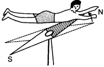
In Ampere’s swimming rule’, imagine a man swimming along the wire in the direction of the current with the face of the man towards the needle, such that current enters his feet and leaves his head, then the direction of the magnetic field produced is such the magnetic held, as shown in the diagram, towards his left hand.
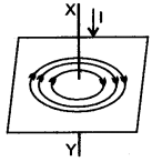
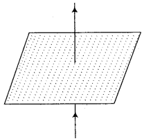
Question 2: The diagram shows a current carrying coil passing through a cardboard sheet. Draw three magnetic lines of force on the board.
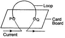
State two factors on which magnitude of magnetic field at the centre depends.
Answer: Figure shows the magnetic lines of force due to current carrying coil.
The magnitude of magnetic field at the centre of coil depend on: (i) the strength of current in the coil, and (ii) the radius of coil.
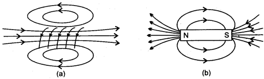
Question 3: Sketch the lines of force of the magnetic field of a solenoid. How does its field compare with that of a bar magnet?
Answer: The magnetic field of a solenoid is very similar to that of a bar magnet. This is shown in figure (a) and (b) which shows, respectively, the lines of force of the magnetic field of a current carrying solenoid and a bar magnet.
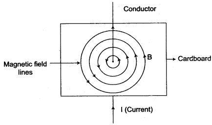
Question 4: In the diagram XY is a straight conductor carrying current in the direction marked by the arrow. The conductor is held vertical by passing it through a horizontal cardboard sheet.
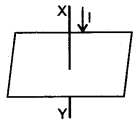
Draw three magnetic lines of force on the board and mark the direction of magnetic field in your diagram. State two factors on which magnitude of magnetic field at a point, depends.
Answer: The magnetic lines of force due to current in the straight conductor XY are shown in figure given alongside. The arrows on the magnetic lines of force shows the direction of magnetic field.
The magnitude of magnetic field at a point depends on:
(i) The strength of current in the conductor, and
(ii) The distance of point from the conductor.
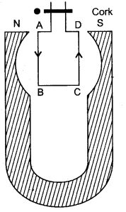
Question 5: State and explain Maxwell’s Cork Screw Rule.
Answer: Maxwell’s Cork Screw Rule:
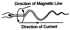
Imagine a right handed cork screw placed parallel to a current carrying conductor such that when it is rotated, it advances in the direction of the current. Then the direction in which the thumb rotates gives the direction of the magnetic lines of forces.
Question 6: State and define the law, which determines the direction of force acting on the current carrying conductor.
Answer: The direction of force acting on a current carrying conductor can be determined by the Fleming’s left hand rule.
Fleming’s left hand rule: Stretch the thumb, the fore finger and the middle finger of your left hand mutually at right angles to each other such that the fore finger point towards the direction of the magnetic field, the middle finger pointing towards the direction of current, then the thumb will indicate the direction of force (or motion) acting on the conductor.
Question 7:(i) A straight wire conductor passes vertically through a piece of cardboard sprinkled with iron filings. Copy the diagram and show the setting of iron filings when a current is passed through the wire in the upward direction and the cardboard is tapped gently. Draw arrows to represent the direction of the magnetic field lines.
(ii) Name the law which helped you to find the direction of the magnetic field lines.
Answer: (i)
(ii) Right hand thumb rule helped to find the direction of magnetic field lines.
Question 8: State and illustrate the rule used for finding the polarity of the faces of a circular coil.
Answer: For finding the polarity of the two faces of a current carrying circular coil, the following rule applies:
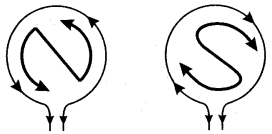
When an observer, looking at the circular coil, finds the current to be flowing in the anti-clockwise direction, then face of the coil behaves like the N-pole of the equivalent magnet. On the other hand, if the’current is seen to flow in the clockwise direction, then face of the coil behaves like the S-pole of the equivalent magnet.
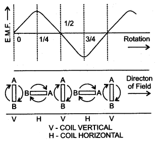
Question 9: A flat coil of wire rotates at a constant speed about an axis perpendicular to a uniform magnetic field. Draw a graph to show how the induced e.m.f. varies relative to the positions of the coil during its one complete rotation. At what position of the coil, the e.m.f. has the maximum value?
Answer:
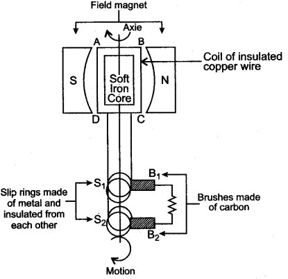
Figure below shows the variation in induced e.m.f. relative to various positions of coil, during its one complete rotation.
The e.m.f. is maximum when the coil is with its plane parallel to the magnetic field.
Question 10: The adjacent diagram shows a small magnet placed near a solenoid. State whether the magnet is attracted or repelled, as the switch is pressed. Give a reason.
Answer:
As the switch is pressed, the magnet will get repelled. The reason is that at the face of solenoid near the north pole of magnet, the current flows in anti-clockwise direction, so the face becomes north pole. The like poles repel, so the magnet is repelled.
Question 11: What is a solenoid? Why do we usually keep its diameter small in comparison to its length?
Answer:
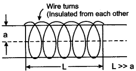
If a conducting wire (coated with an insulating paint or varnish) is closely wound on a (long) cylindrical core, the resulting coil is referred to as solenoid. It is usual to keep the diameter of the solenoid small compared to its length. This is done to bring about a greater degree of uniformity (and simplicity) in the axial magnetic field of the solenoid.
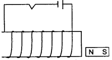
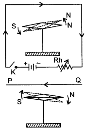
Question 12: What is an electromagnet? What do you know about the simplest form of an electromagnet?
Answer:
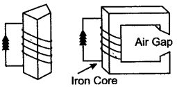
The electromagnet is a temporary magnet which can be magnetized or demagnetized in a very short time as per our requirements. In the simplest form, an electromagnet consists simply of a soft iron core around which a large number of turns of insulated wire are wound. Two of the simple forms of an electro magnet are shown in the figure alongside.
Question 13: Draw a labelled diagram to make an electromagnet from a soft iron bar. Mark the polarity at its ends in your diagram. What precaution would you observe while making it?
Answer: The labelled diagram is shown in figure.
Precaution: The source of current must be the D. C. battery.
Question 14: You have been provided with a solenoid AB.
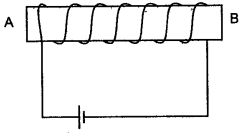
(i) What is the polarity at end A?
(ii) Give one advantage of an electromagnet over a permanent magnet.
Answer. (i) North pole.
(ii) Electromagnet is a very strong magnet as compared to a permanent magnet.
Question 15: State the function of a split ring in D.C. motor.
Answer: When the coil of a D. C motor turns through 180°, the split ring reverses the direction of the current in the coil from CBAD to DABC.
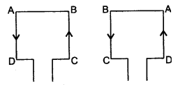
In this way, the coil continues to rotate continuously in the same direction and positive and negative polarities are maintained.
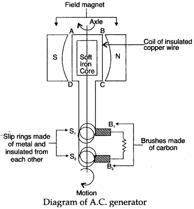
Question 16: Draw a labelled diagram of an A.C. generator.
Answer: Figure below shows the variation in induced e.m.f. relative to various positions of coil, during its one complete rotation. The e.m.f. is maximum when the coil is with its plane parallel to the magnetic field.
Question 17: State change that you would make to convert an A.C. generator into a D.C. generator. Illustrate the change by a diagram.
Answer: As shown in the diagram the only change is that both the slip-rings of an A.C. generator are replaced by a split-ring (X-Y) (a ring split in two halves) which acts as a commutator or current-reverser.
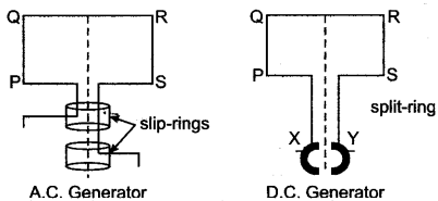
The other parts in both are the same. By this device the current in the external circuit becomes unidirectional.
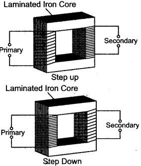
Question 18: Draw a labelled diagram to show the various parts of a step-up transformer and step down transformer.
Answer: Step-up transformer is used to change low voltage alternating e.m.f. to high voltage alternating e.m.f. Its essential parts are shown in the given diagram:
Question 19: (i) Draw a clear labelled diagram of an electric bell.
(ii) Explain in brief, its working.
(iii) What material is used for the core of an electric bell? State the reason.
Answer: (i)
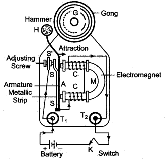
(ii) An electric bell is one of the most common application of an electromagnet.
Construction and wiring: An electric bell shown in above fig.
The main parts of the bell are:
- A horse-shoe electromagnet M, having iron core,
- Soft iron armature A,
- A hammer H,
- A gong G,
- A metallic spring strip SS,
- An adjusting screw SS,
- A switch (or bell-push) K, and
- A battery.
Working and function of each part: The working of an electric bell is based on the magnetic effect of current. When the electric circuit is closed by pressing the switch K, the current flows through the coil CC and the core of electromagnet gets magnetised and therefore it attracts the armature A as shown A, the hammer H strikes the gong G and the bell rings.
At the moment, when the armature, due to attraction, moves towards the electromagnet, the connection between the strip SS and the screw S’ breaks which stops the flow of current in the circuit. Consequently, the electromagnet loses magnetism (i.e.r it gets demagnetised) and the armature A flies back to its original position due to the spring effect of the strip SS. Now the armature again touches the screw S’, resulting in the flow of current in the circuit. The electromagnet regains its magnetism and the armature A is again attracted, so the hammer H strikes the gong G again.
This process of make and break of the circuit goes on the hammer strikes the gong repeatedly and the bell rings so long as the switch K is kept pressed.
(iii) The core of the electromagnet is made of soft iron because: Firstly, it increases the intensity of the magnetic field of the electromagnet and secondly it easily get demagnetized when no current flows in the turns of the coil of insulated copper wire wound over the core, thus helping in the smooth working of the electric bell.
Figure Based Long Answers
Question 1: Describe a set up for plotting the magnetic lines of force in:
(i) A straight wire, (ii) A circular coil and (iii) A straight solenoid.
Answer: (i) A set-up for plotting the magnetic lines of force in a straight wire is shown in the diagram. A smooth cardboard with a hole at the centre is placed horizontally and a wire passes vertically through the hole. Some iron filings are sprinkled on the card-board and an electric current is passed through the wire. On slightly tapping the card-board the iron filing arrange themselves in concentric circle around the wire, as shown in the diagram. The direction of magnetic lines of force is clockwise since the the current in the straight wire is flowing downwards. If the current flow is upwards then the direction of lines of force is anti-clockwise. (See diagram (a) and (b))
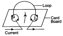
(ii) Arrangement of the apparatus is the same, as in (a), only the wire is in the form of a circular coil and is passing through two holes, A and B in the cardboard. On passing the current through the circular coil, iron filings sprinkled on the horizontal surface of the smooth cardboard make a pattern of the lines of force, as shown in the diagram.
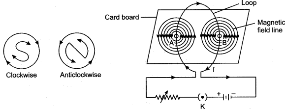
One face of the coil has north polarity while the other face shows south polarity, in accordance with the following rule: Looking at one face of the coil, if the direction of the current is anti-clockwise, that face has north polarity and the opposite face has south polarity.
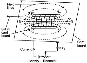
(iii) The accompanying diagram illustrates the pattern of magnetic lines of force in a straight solenoid. As shown in the diagram, the solenoid behaves like a cylindrical magnet having North and South poles at free ends. If the current flows in the reverse direction, the polarity at the free ends is also reversed.
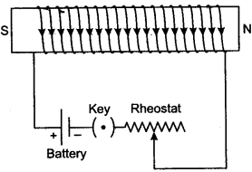
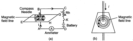
Question 2: Describe an experiment to show that there is a magnetic field around a current carrying conductor.
Answer: In 1820 Oersted discovered that when an electric current passes through a conductor, a magnetic field is produced around the conductor, i.e., so long the current continues to flow through the conductor, it behaves like a magnet. This can be illustrated by a simple experiment described below.
Take a magnetic needle pivoted at its centre and free to move in horizontal plane.
Take a thick and insulated copper wire PQ and connect it to the battery circuit through a key K and a variable resistance Rh.
Hold the wire PQ parallel and just above the axle of the magnetic needle and press the key. It is observed that N-pole of the needle points towards the west so long the current continues to flow through the wire. It is also observed that if the current is increased or decreased, the deflection of the magnetic needle also increases or decreases.
If the direction of the current through PQ is reversed, i.e., if the current flows from Q to P, then N-pole of the needle is deflected towards east, this experiment shows that a magnetic field is set up around a current carrying conductor.
Question 3: Diagram shows a rectangular coil ABCD, suspended freely between the concave pole pieces of a permanent horse shoe magnet, such that the plane of coil is parallel to magnetic field.
(i) State your observation, when current is switched on.
(ii) Give an explanation for your observation in (i).
(iii) State the rule, which will help you to find the motion of rotation of coil.
(iv) In which position will the coil ultimately come to rest?
(v) State four ways of increasing the magnitude of force acting on the coil.
Answer:
(i) The coil ABCD will turn. The arm AB of the coil will move out of the plane of paper and arm CD into the plane of paper.
Thus, coil will turn in anticlockwise direction.
(ii) A magnetic field is set up by the coil due to the passage of electric current. The magnetic field of the coil is at right angles to the magnetic field of permanent magnet. Thus, a magnetic couple acts, which turns the coil.
(iii) Fleming’s left rule: It states : Stretch the thumb, the forefinger and the middle finger of left hand, such that forefinger points in the direction of magnetic field; middle finger points in the direction of current. Then, the thumb points in the direction of motion of conductor.
(iv) The coil will come to rest at right angles to the direction of magnetic field.
(v) (a) By increasing the number of turns in coil.
(b) By increasing the area of cross-section of coil.
(c) By placing laminated soft iron core within the coil.
(d) By increasing the magnitude of current coil.
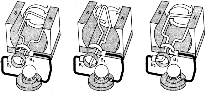
Question 4: Figures 1 to 3 show the working of a simple A.C. generator. Study the diagrams and answers of the following questions.
(i) State and explain the principle underlying the working of a simple generator.
(ii) Where is the loop of wire placed?
(iii) What happens when the loop is rotated?
(iv) Indicate the direction of the current flow through the wire for the first half of the turn (Figure 1). Name and state the rule used in finding the direction of the current.
(v) Indicate the direction of the current for the case shown in figure 2.
(vi) Indicate the direction of current in the outer circuit (i.e., electric bulb) in figure 1 and in figure 3.
(vii) What type of current is shown in the above diagrams? Explain.
Answer:
(i) The generator works on the principle of Electromagnetic Induction. Whenever the flux passing through a closed circuit changes, e.m.f. is induced in it and a current begins to flow. Its direction is given by Fleming’s Right Hand Rule or Lenz Law. As long as the loop is moving within the magnetic field an electric current will flow.
(ii) The loop of wire is placed between the two poles of a ‘U’-shaped magnet.
(iii) When the loop of wire is rotated between the two poles of a ‘U’-shaped magnet an electric current flows through the wire.
(iv) As rotation of the coil is the clockwise direction and the direction of magnetic field is from right to left, the current will flow in the anticlockwise direction, i.e., from B2 and B1. The law used is Lenz’s law.
Lenz’s law: “The direction of the induced e.m.f. is such that it opposes the change responsible for its production.”
(v) No electric current flows when the loop of wire is halfway through the turn, i.e., at an angle of 90° [as sin 90° = 0.]
(vi) Figure 1: From brush B2 to B1
Figure 3: From brush B1 to B2
(vii) The type of current shown is an alternating current or A.C. current. When the loop of wire makes the second half of the turn (fig., the direction of the electric current through the bulb is reversed and it flows back in the opposite direction.
Question 5: Copy the given diagram of a transformer and complete it. Name the parts A and B. Name the part you have drawn to complete the diagram. What is the material of this part? Is this transformer a step-up or step-down? Give reason.
Answer: The completed diagram is given below:
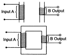
The part A is called primary coil. The part B is called secondary coil.
The part drawn is called core.
The material of core is soft iron.
(i) This transformer is step-down since it has more turns in primary coil than in secondary coil.
(ii) A step-up transformer has more turns in secondary coil as compared to that in primary coil, while a step-down transformer has more turns in primary coil as compared to that in secondary coil.
(iii) In a step-up transformer the wire in the primary coil is thicker as compared to that in secondary coil, while in a step down transformer the wire in secondary coil is thicker as compared to that in primary coil.
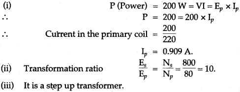
Question 6: The power supply to the primary coil of a transformer is 200 W. Find
(i) Current in primary coil if the e.m.f. supply to it is equal to 220V.
(ii) The number of turns in the primary coil is equal to 80 and that in secondary is 800. What is the transformation ratio?
(iii) Name the type of transformer.
(iv) What will be the output voltage?
(v) What is the current in the secondary coil for an ideal transformer?
(vi) What is the output power?
(vii) Is output and input power equal?
(viii) Compare the current flowing in a secondary coil and in a primary coil.
Answer:
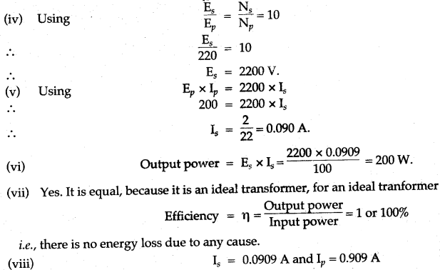
Less current flows through the secondary coil than in the primary coil because it is a step-up transformer.
Short Numericals
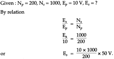
Question 1: The primary coil of a transformer has 200 turns while the secondary coil has 1000 turns. What type of transformer is this? if the input voltage is 10V, what will be the output voltage?
Solution: The transformer is step-up transformer.
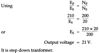
Question 2: Applying e.m. f to primary coil is 210 V. If the number of turns in primary coil is 200 turns and that of in secondary coil is 20 turns, then find out the output voltage. Name the type of the transformer.
Solution:
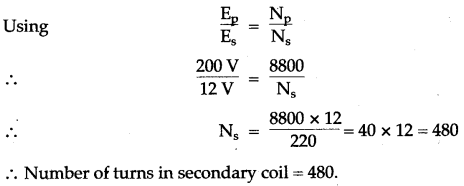
Question 3: A transformer lowers e.m.f. 220 V to 12 volts. If the number of turns in primary are 8800, how many turns are in secondary coil?
Solution:
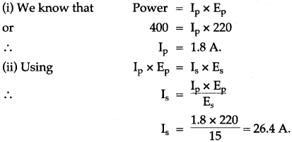
Question 4: A transformer lowers e.m.f. from 220 V to 15 V. If 400 W power is given in primary, calculate (i) the current in primary coil and (ii) the current in secondary coil.
Solution:
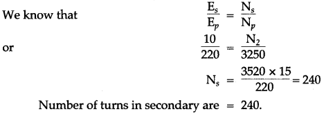
Question 5: A transformer lowers e.m.f. from 220 V to 15 V. If the number of turns in primary are 3520, how many turns are in the secondary coil?
Solution:
For More Resources