Magnetic Field Due to a Current Carrying Straight Conductor
The Magnetic Field Due to a Current in a Straight Wire:
- The magnetic field lines are concentric circles as shown in Figure.
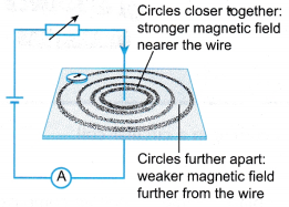
- The spacing between the circles increases as you move away from the wire. This shows that the strength of the magnetic field decreases as the distance from the wire increases.
- At a certain point in the magnetic field, the strength of the field will increase if the current is increased.
- The current can be increased by:
(a) Adding more cells in series at the power supply
(b) Reducing the resistance of the rheostat
(c) Using a shorter wire to reduce the resistance
(d) Using a thicker wire to reduce the resistance - The direction of the magnetic field can be determined using Ampere’s right-hand grip rule. Imagine the wire is gripped using your right hand with your thumb pointing in the direction of the current. The other four fingers show the direction of the magnetic field round the wire, as shown in Figure (a).
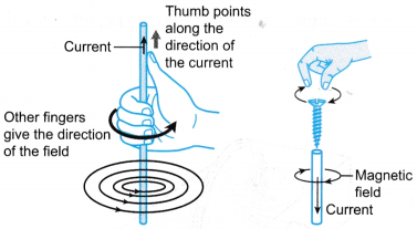
- The direction of the magnetic field can also be determined by Maxwell’s Corkscrew Rule- Imagine a screw being turned into the wire along the direction of the current. The direction of rotation of the screw is the direction of the magnetic field as shown in Figure (b).
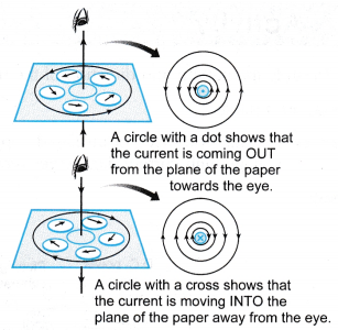
- Figure shows the magnetic field due to a straight wire seen from various angles.
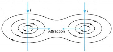
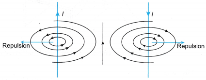
- If two straight wires are placed side by side, the magnetic fields produced by the currents in them will combine to form a resultant field.
(a) Figure shows the magnetic field for two straight parallel wires carrying current in the same direction. The wires attract with each other.
 (b) Figure shows the magnetic field for two straight parallel wires carrying current in opposite directions. The wires repel with each other.
People also ask
- What is magnetic force on a current carrying conductor?
- What factors affect the strength of an electromagnet?
- What is the Magnetic Field?
- What Is Magnetic Effect Of Electric Current?
- Oersted Experiment on Magnetic Effect of Current
- How do you Determine the Direction of the Magnetic Field?
- What is the Meaning of Magnetic Force?
- How Does a Transformer Work?
- Who discovered the magnet?
- How does a magnet work?
- What are the Different Types of Magnets?
- Is an electromagnet a temporary or a permanent magnet?
- What is the use of magnet?
- How does an electric bell work using electromagnets?
Magnetic Field Due to a Current Carrying Straight Conductor Experiment
Aim: To study the pattern and direction of the magnetic field due to a current in a straight wire.
Material: Iron filings
Apparatus: Cardboard, thick insulated copper, 4 plotting compasses, low voltage high current d.c. power supply, connecting wires
Method: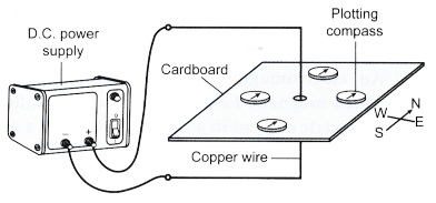
- The apparatus is set up as shown in Figure.
- The d.c. power supply is switched on and the direction shown by the compasses is noted.
- The d.c. power supply is switched off. The compasses are removed and some iron filings are sprinkled on the cardboard.
- The d.c. power supply is switched on again. The cardboard is tapped a few times and the pattern formed by the iron filings is noted.
Observation: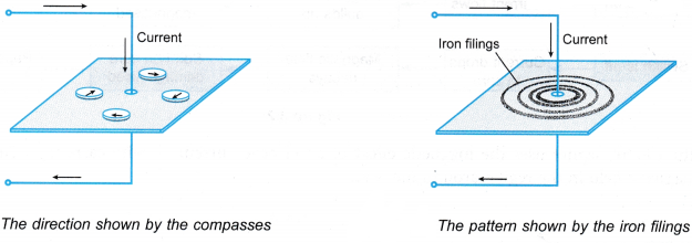
Discussion:
- The iron filings show the pattern of the magnetic field while the compasses show the direction of the field.
- A thick copper wire is used so that a larger current will flow to produce a stronger magnetic field.
- The d.c. power supply should be switched off after making the observations so that the copper wire will not be overheated.
Magnetic Field Due to Current through a Circular Loop
The Magnetic Field Due to a Current in a Coil:
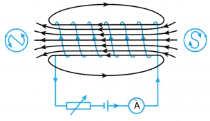
- Figure shows the magnetic field produced by a current in a circular coil.
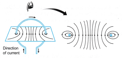
- The magnetic lines are closest to each other at the centre of the coil. This shows that at the centre of the coil, the magnetic field is the strongest.
- The strength of the magnetic field increases when:
(a) The current in the coil is increased
(b) The coil has more turns
(c) A coil of smaller radius is used
Magnetic Field Due to Current through a Circular Loop Experiment
Aim: To study the pattern and direction of the magnetic field due to a current in a circular coil.
Material: Iron filings
Apparatus: Circular coil made of insulated copper wire mounted on a plastic frame, 3 plotting compasses, low voltage high current d.c. power supply, connecting wires
Method:
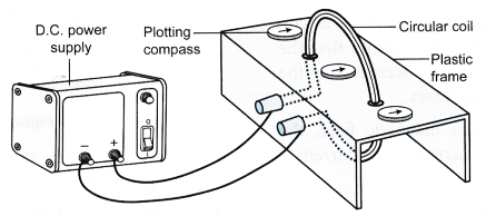
- The apparatus is set up as shown in Figure.
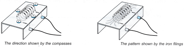
- The d.c. power supply is switched on and the direction shown by the compasses is noted.
- The d.c. power supply is switched off. The compasses are removed and some iron filings are sprinkled on the plastic frame.
- The d.c. power supply is switched on again. The plastic frame is tapped a few times and the pattern formed by the iron filings is noted.
Observation: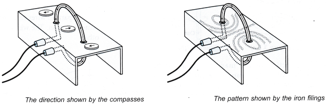 Discussion:
- It is better to have more turns of the copper wire. The magnetic field from each turn of wire will combine together to form
- a stronger field. This enables the iron filings to show clearly the pattern of the field.
- The d.c. power supply should be switched off after making the observations so that the copper wires will not be overheated.
Magnetic Field Due to a Solenoid Carrying Current
The Magnetic Field Due to a Current in a Solenoid:
- The magnetic field for a solenoid has a similar pattern to the magnetic field of a bar magnet, as shown in Figure. One end of the solenoid is a North pole while the other end is a South pole.
- The polarity at the ends of the solenoid can be determined by:
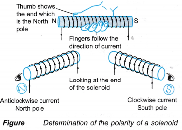 (a) Using the right-hand grip rule. Hold the solenoid using your right hand with your four fingers curled around the solenoid along the direction of the current. The thumb will point to the end that is the North pole.
(b) Looking at the end of the solenoid. A clockwise current indicates a South pole while an anticlockwise current indicates a North pole.
Magnetic Field Due to a Solenoid Carrying Current Experiment
Aim: To study the pattern and direction of the magnetic field due to a current in a solenoid.
Material: Iron filings
Apparatus: Solenoid made of insulated copper wire mounted on a plastic frame, 4 plotting compasses, low voltage high current d.c. power supply, connecting wires
Method: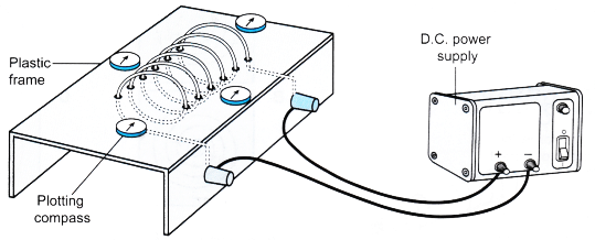
- The apparatus is set up as shown in Figure.
- The d.c. power supply is switched on and the direction shown by the compasses is noted.
- The d.c. power supply is switched off. The compasses are removed and some iron filings are sprinkled on the plastic frame.
- The d.c. power supply is switched on again. The plastic frame is tapped a few times and the pattern formed by the iron filings is noted.
Observation:
Discussion:
- It is better to have more turns of thick copper wire. The thicker wire has a smaller resistance so that the current will be larger. Each turn of wire forms its magnetic field. The magnetic field from all the turns of wire will combine together to form a stronger field. This enables the iron filings to show clearly the pattern of the field.
- The d.c. power supply should be switched off after making the observations so that the copper wires will not be overheated.